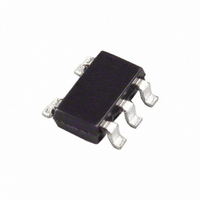
ADR395BUJZ-R2 Analog Devices Inc, ADR395BUJZ-R2 Datasheet - Page 18

ADR395BUJZ-R2
Manufacturer Part Number
ADR395BUJZ-R2
Description
IC VREF W/SHUTDN 5V TSOT23-5
Manufacturer
Analog Devices Inc
Series
ADR39r
Datasheet
1.ADR395AUJZ-REEL7.pdf
(20 pages)
Specifications of ADR395BUJZ-R2
Temperature Coefficient
9ppm/°C
Reference Type
Series
Voltage - Output
5V
Tolerance
±0.1%
Voltage - Input
5.3 ~ 15 V
Number Of Channels
1
Current - Quiescent
140µA
Current - Output
5mA
Operating Temperature
-40°C ~ 125°C
Mounting Type
Surface Mount
Package / Case
TSOT-23-5, TSOT-5, TSOP-5
Topology
Series
Input Voltage
4.3V To 15V
Reference Voltage
5V
Reference Voltage Tolerance
5mV
Voltage Reference Case Style
TSOT
No. Of Pins
5
Lead Free Status / RoHS Status
Lead free / RoHS Compliant
Current - Cathode
-
Lead Free Status / RoHS Status
Lead free / RoHS Compliant, Lead free / RoHS Compliant
ADR390/ADR391/ADR392/ADR395
High Power Performance with Current Limit
In some cases, the user may want higher output current
delivered to a load and still achieve better than 0.5% accuracy
out of the ADR39x. The accuracy for a reference is normally
specified on the data sheet with no load. However, the output
voltage changes with load current.
The circuit shown in Figure 44 provides high current without
compromising the accuracy of the ADR39x. The series pass
transistor, Q1, provides up to 1 A load current. The ADR39x
delivers only the base drive to Q1 through the force pin. The
sense pin of the ADR39x is a regulated output and is connected
to the load.
The Transistor Q2 protects Q1 during short-circuit limit faults
by robbing its base drive. The maximum current is
A similar circuit function can also be achieved with the
Darlington transistor configuration, as shown in Figure 45.
Figure 44. ADR39x for High Power Performance with Current Limit
I
LMAX
V
IN
≈ 0.6 V/ R
V
V
V
OUT (FORCE)
OUT (SENSE)
ADR39x
IN
R1
4.7kΩ
SHDN
Figure 43. A General-Purpose Current Source
GND
V
IN
SHDN
V
V
OUT (SENSE)
I
IN
SY
V
ADR39x
S
OUT (FORCE)
(I
U1
SET
)
GND
ADJUST
0.1µF
Q2N2222
I
SY
Q2
R
R1
L
I
I
SET
OUT
= I
R1
P1
SET
R
R
R
+ I
S
L
SET
SY
Q1
Q2N4921
(I
I
L
SET
)
Rev. G | Page 18 of 20
(6)
CAPACITORS
Input Capacitor
Input capacitors are not required on the ADR39x. There is no
limit for the value of the capacitor used on the input, but a 1 μF
to 10 μF capacitor on the input improves transient response in
applications where the supply suddenly changes. An additional
0.1 μF in parallel also helps reduce noise from the supply.
Output Capacitor
The ADR39x does not require output capacitors for stability under
any load condition. An output capacitor, typically 0.1 μF, filters
out any low level noise voltage and does not affect the operation
of the part. On the other hand, the load transient response can
improve with the addition of a 1 μF to 10 μF output capacitor in
parallel. A capacitor here acts as a source of stored energy for a
sudden increase in load current. The only parameter that degrades
by adding an output capacitor is the turn-on time, and it depends
on the size of the capacitor chosen.
V
IN
–100
–150
–50
150
100
Figure 46. ADR391 Typical Long-Term Drift over 1000 Hours
50
0
0
R1
4.7kΩ
100
Figure 45. ADR39x for High Output Current
SHDN
V
V
OUT (SENSE)
IN
with Darlington Drive Configuration
ADR39x
V
200
OUT (FORCE)
U1
300
GND
400
TIME (Hours)
500
600
R
S
700
Q1
Q2N2222
800
R
L
900
Q2
Q2N4921
1000


