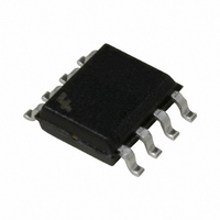
FAN7554DTF Fairchild Semiconductor, FAN7554DTF Datasheet - Page 10

FAN7554DTF
Manufacturer Part Number
FAN7554DTF
Description
IC CTRLR PWM CURRENT MODE 8SOIC
Manufacturer
Fairchild Semiconductor
Datasheet
1.FAN7554DTF.pdf
(22 pages)
Specifications of FAN7554DTF
Pwm Type
Current Mode
Number Of Outputs
1
Frequency - Max
500kHz
Duty Cycle
98%
Voltage - Supply
9 V ~ 30 V
Buck
No
Boost
No
Flyback
Yes
Inverting
No
Doubler
No
Divider
No
Cuk
No
Isolated
Yes
Operating Temperature
-25°C ~ 85°C
Package / Case
8-SOIC (3.9mm Width)
Frequency-max
500kHz
Output Current
1 A
Switching Frequency
500 KHz
Mounting Style
SMD/SMT
Maximum Operating Temperature
+ 85 C
Minimum Operating Temperature
- 25 C
Lead Free Status / RoHS Status
Lead free / RoHS Compliant
Other names
FAN7554DTFTR
FAN7554DTF_NL
FAN7554DTF_NLTR
FAN7554DTF_NLTR
FAN7554DTF_NL
FAN7554DTF_NLTR
FAN7554DTF_NLTR
Available stocks
Company
Part Number
Manufacturer
Quantity
Price
Part Number:
FAN7554DTF
Manufacturer:
FAIRCHILD/仙童
Quantity:
20 000
FAN7554
Feedback
As shown in figure16, the internal oscillator clock turns on the MOSFET. The feedback comparator operates to turn it off
again, when the MOSFET current reaches a set value proportional to Vfb. The feedback capacitor Cfb is charged by the inter-
nal current sources , 1mA and 5uA, and is discharged by the secondary side photo-coupler to control the output voltage.
Delayed Shutdown
During the normal operation, the feedback voltage is between 0~3V. If the output terminal overloads or an error happens to
the feedback loop, the delayed shutdown circuit operates. When the feedback voltage is less than 3V, the feedback capacitor is
charged by current sources, 1mA and 5uA; when the feedback voltage becomes greater than 3V, the capacitor is charged by the
5uA current source because diode D1 turns off. When the feedback voltage is less than 3V, the charge slope becomes an expo-
nential function and, when it is greater than 3V, the charge slope becomes linear. When the feedback voltage reaches almost
6V, the FAN7554 shuts down. The shut down circuit is configured for
auto-restart, so it automatically restarts when Vcc reaches the under voltage 9V.
10
Cfb
Cfb
Cfb
Cfb
FB
FB
Vfb
Vfb
1
1
FB
FB
6V
6V
1
1
1mA
1mA
5uA
5uA
1mA
1mA
5uA
5uA
D1
D1
5V
5V
5V
5V
Vcc
Vcc
Vcc
Vcc
Figure 17-A . Delayed Shutdown & Feedback Circuit
Over Current
Over Current
Comparator
Comparator
2R
2R
2R
2R
R
R
Vfb/3
Vfb/3
R
R
Figure 16. Feedback & PWM Circuit
UVLO - out
UVLO - out
OSC
OSC
OSC
OSC
S
S
R
R
Q
Q
S
S
R
R
Shutdown
Shutdown
S
S
R
R
Q
Q
Q
Q
FAN7554
FAN7554
FAN7554
FAN7554
3
3
6
6
OUT
OUT
IS
IS
3
3
6
6
OUT
OUT
IS
IS
Rs
Rs
Rs
Rs
DRIN
DRIN
Vsense
Vsense
DRIN
DRIN


