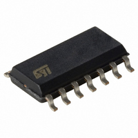
TSM108IDT STMicroelectronics, TSM108IDT Datasheet

TSM108IDT
Specifications of TSM108IDT
Available stocks
Related parts for TSM108IDT
TSM108IDT Summary of contents
Page 1
VOLTAGE AND CURRENT STEPDOWN PWM CONTROLLER OUTPUT HIGH SIDE CURRENT SENSING PRECISE CC/CV REGULATION ADJUSTABLE SWITCHING FREQUENCY ADJUSTABLE OVP/UVP UVLO THRESHOLDS STANDBY MODE FEATURE SUSTAINS 60V MINIMAL EXTERNAL COMPONENTS COUNT DRIVES EXTERNAL P-CHANNEL MOSFET OR PNP BIPOLAR TRANSISTORS DESCRIPTION TSM108 ...
Page 2
TSM108 PIN DESCRIPTION Name Pin VCC 1 Supply voltage of both the signal part and the gate drive !STBY 2 Standby Command; when Low, the device goes in standby GND 3 Ground. Current return for both the gate drive and ...
Page 3
ELECTRICAL CHARACTERISTICS T = 25° 12V (unless otherwise specified) amb CC Symbol Parameter CURRENT CONSUMPTION I Current Consumption CC STANDBY I Current Consumption in Standby Mode stby V Input Standby Voltage High Impedance sh V Input Standby Voltage ...
Page 4
TSM108 DETAILED INTERNAL SCHEMATIC 4/13 ...
Page 5
OSCILLATOR FREQUENCY VERSUS TIMING CAPACITOR TSM108 AS A STAND ALONE DC/DC CONVERTER FOR CIGARETTE LIGHTER ACCESSORIES TSM108 5/13 ...
Page 6
PRINCIPLE OF OPERATION AND APPLICATION HINTS Description of a DC/DC step down battery charger 1. Voltage and Current Controller The device has been designed to drive an external P-Channel MOSFET in PWM mode and in Step Down topology. Its two ...
Page 7
Gate Drive The Gate Drive stage is directly commanded from the PWM output signal. The Gate Drive stage is a totem pole Mosfet stage which bears different On resistances in order to ensure a slower turn ON than turn ...
Page 8
TSM108 7. Standby Mode In order to reduce to a minimum the current con- sumption of the TSM108 when in inactive phase, the Standby mode (!Stby pin of TSM108) imposes a complete OFF state of the P-Channel MOSFET, as well ...
Page 9
Inductor The minimum inductor value to choose should ap- ply to Lmin = ( where R = Vout / Iout = 9.6W and where D = Vout / Vin = 0.5 Therefore, Lmin = ...
Page 10
TSM108 Mosfet: Pchannel Mosfet: Rdson = 100mΩ, Ciss = 1nF. Driver: TSM108 PWM frequency: 100kHz Free wheel diode 0.7V Shunt: Rsense = 330mΩ The efficiency (η regulator is defined as the ratio of the charging power ...
Page 11
Measured Performances The few following curves show the measured per- formances of TSM108 used in DC/DC step down 12.1. Voltage and Current Control, Efficiency Performances using a Pchannel MOSFET: CV & CC Regulation - Switching duty cycle vs Iout ...
Page 12
TSM108 12.2. Voltage and Current Control, Efficiency Performances using a PNP bipolar transistor Vout & duty cycle versus Iout 0.05 Efficiency & duty cycle versus Iout 80% 70% 60% 50% 40% ...
Page 13
... No license is granted by implication or otherwise under any patent or patent rights of STMicroelectronics. Specifications mentioned in this publication are subject to change without notice. This publication supersedes and replaces all information previously supplied. STMicroelectronics products are not authorized for use as critical components in life support devices or systems without express written approval of STMicroelectronics. © ...


