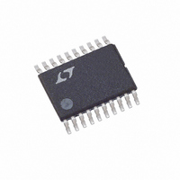
LTC3778EF#PBF Linear Technology, LTC3778EF#PBF Datasheet - Page 12

LTC3778EF#PBF
Manufacturer Part Number
LTC3778EF#PBF
Description
IC STEP-DWN CONTRLR SYNC 20TSSOP
Manufacturer
Linear Technology
Type
Step-Down (Buck)r
Datasheet
1.LTC3778EFPBF.pdf
(24 pages)
Specifications of LTC3778EF#PBF
Internal Switch(s)
No
Synchronous Rectifier
Yes
Number Of Outputs
1
Voltage - Output
0.6 ~ 32.4 V
Current - Output
2A
Frequency - Switching
Adjustable
Voltage - Input
4 ~ 36 V
Operating Temperature
-40°C ~ 85°C
Mounting Type
Surface Mount
Package / Case
20-TSSOP
Primary Input Voltage
36V
No. Of Outputs
1
Output Voltage
36V
Output Current
2A
No. Of Pins
20
Operating Temperature Range
-40°C To +85°C
Msl
MSL 1 - Unlimited
Rohs Compliant
Yes
Lead Free Status / RoHS Status
Lead free / RoHS Compliant
Power - Output
-
Available stocks
Company
Part Number
Manufacturer
Quantity
Price
APPLICATIO S I FOR ATIO
LTC3778
load current increases. By lengthening the on-time slightly
as current increases, constant frequency operation can be
maintained. This is accomplished with a resistive divider
from the I
required will depend on the parasitic resistances in the
specific application. A good starting point is to feed about
25% of the voltage change at the I
shown in Figure 3a. Place capacitance on the V
filter out the I
resistor load on I
and degrades load regulation, which can be avoided by
using the PNP emitter follower of Figure 3b.
Inductor Selection
Given the desired input and output voltages, the inductor
value and operating frequency determine the ripple
current:
Lower ripple current reduces core losses in the inductor,
ESR losses in the output capacitors and output voltage
ripple. Highest efficiency operation is obtained at low
frequency with small ripple current. However, achieving
12
Figure 3. Correcting Frequency Shift with Load Current Changes
I
L
INTV
TH
V
V
V
OUT
f L
OUT
OUT
TH
CC
pin to the V
variations at the switching frequency. The
2N5087
TH
R
R
R
10k
30k
VON2
100k
VON1
VON1
3k
1
U
reduces the DC gain of the error amp
Q1
V
R
10k
V
OUT
VON2
C
IN
R
C
U
C
ON
(3a)
(3b)
pin and V
C
0.01 F
C
0.01 F
C
VON
VON
C
TH
R
C
W
pin to the V
V
I
V
I
TH
TH
LTC3778
LTC3778
ON
ON
OUT
3778 F03a
3778 F03b
. The values
U
ON
ON
pin as
pin to
this requires a large inductor. There is a tradeoff between
component size, efficiency and operating frequency.
A reasonable starting point is to choose a ripple current
that is about 40% of I
occurs at the highest V
does not exceed a specified maximum, the inductance
should be chosen according to:
Once the value for L is known, the type of inductor must be
selected. A variety of inductors designed for high current,
low voltage applications are available from manufacturers
such as Sumida, Panasonic, Coiltronics, Coilcraft and
Toko.
Schottky Diode D1 Selection
The Schottky diode D1 shown in Figure 1 conducts during
the dead time between the conduction of the power
MOSFET switches. It is intended to prevent the body diode
of the bottom MOSFET from turning on and storing charge
during the dead time, which can cause a modest (about
1%) efficiency loss. The diode can be rated for about one
half to one fifth of the full load current since it is on for only
a fraction of the duty cycle. In order for the diode to be
effective, the inductance between it and the bottom MOS-
FET must be as small as possible, mandating that these
components be placed adjacently. The diode can be omit-
ted if the efficiency loss is tolerable.
C
The input capacitance C
wave current at the drain of the top MOSFET. Use a low
ESR capacitor sized to handle the maximum RMS current.
This formula has a maximum at V
I
RMS
IN
I
L
RMS
and C
= I
OUT(MAX)
f I
OUT
I
OUT MAX
V
L MAX
OUT
(
Selection
(
/ 2. This simple worst-case condition is
)
)
V
OUT(MAX)
1
V
OUT
IN
IN
IN
. To guarantee that ripple current
V
IN MAX
is required to filter the square
V
OUT
(
V
V
OUT
. The largest ripple current
IN
)
– 1
IN
= 2V
OUT
, where
3778f


