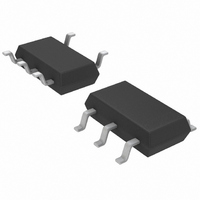
LT1935ES5#TRM Linear Technology, LT1935ES5#TRM Datasheet - Page 5

LT1935ES5#TRM
Manufacturer Part Number
LT1935ES5#TRM
Description
IC MULTI CONFIG ADJ 2A TSOT23-5
Manufacturer
Linear Technology
Type
Step-Up (Boost), Flyback, Sepicr
Datasheet
1.LT1935ES5TRMPBF.pdf
(8 pages)
Specifications of LT1935ES5#TRM
Internal Switch(s)
Yes
Synchronous Rectifier
No
Number Of Outputs
1
Voltage - Output
1.27 ~ 38 V
Current - Output
2A
Frequency - Switching
1.2MHz
Voltage - Input
2.3 ~ 16 V
Operating Temperature
-40°C ~ 85°C
Mounting Type
Surface Mount
Package / Case
TSOT-23-5, TSOT-5, TSOP-5
Lead Free Status / RoHS Status
Contains lead / RoHS non-compliant
Power - Output
-
Other names
LT1935ES5
LT1935ES5
LT1935ES5
Available stocks
Company
Part Number
Manufacturer
Quantity
Price
APPLICATIONS
Inductor Selection
Use inductors that are intended for high frequency power
applications. The saturation current rating should be at
least 2A. The RMS current rating, which is usually based
on heating of the inductor, should be higher than the
average current in the inductor in your application. For
best efficiency, the DC resistance should be less than
100mΩ.
A good first choice for the inductor value results in a ripple
current that is 1/3 of the maximum switch current:
I
switching frequency. At lower duty cycles (less than 70%),
this value can be lowered somewhat in order to use a
physically smaller inductor.
Table 1 lists several inductor manufacturers, along with
part numbers for inductors that are a good match to the
LT1935.
Table 1. Inductor Suppliers
Supplier
Sumida
Coiltronics/Cooper
Wurth Elektronik
Coilcraft
Diode Selection
Use a Schottky rectifier with a 1A or higher current rating,
such as the On Semiconductor MBRM120. Its 20V reverse
voltage rating is adequate for most applications. Higher
output voltages may require a 30V of 40V diode.
Capacitor Selection
Use capacitors with low ESR (equivalent series resis-
tance). In most cases, multilayer ceramic capacitors are
the best choice. They offer high performance (very low
ESR) in a small package. Use only X5R or X7R types; they
maintain their capacitance over temperature and applied
voltage. Other suitable capacitor types include low-ESR
tantalum capacitors that are specified for power applica-
tions, and newer types of capacitors such as Sanyo’s
POSCAP and Panasonic’s SP CAP.
MAX
..
L = 3 (V
is the maximum switch current of 2A and f is the
IN
/V
OUT
) (V
U
OUT
Model Prefix
CDRH4D18, CDRH4D28,
CDRH5D18, CDRH5D28, CR43
SD10, SD12, SD18, SD20
WE-PD2S, WE-PD3S, WE-PD4S
MSS5131, MSS6132, DO1608
INFORMATION
U
– V
IN
)/(I
MAX
W
• f)
U
Use a 4.7µF ceramic capacitor to bypass the input of the
LT1935. Be aware that the switching regulators require a
low impedance input supply. Additional bulk capacitance
may be required if the LT1935 circuit is more than a few
inches away from the power source. If there are low ESR
capacitors nearby, the input bypass capacitor can be
reduced to 2.2µF.
The output capacitor supports the output under transient
loads and stabilizes the control loop of the LT1935. Look
at the typical application circuits as a starting point to
choose a value. Generally, a higher output capacitance is
required at higher load currents and lower input voltages.
Figure 3 shows transient response of the circuit in Fig-
ure 1. The load is stepped from 200mA to 400mA and back
to 200mA. The transient performance can be improved by
increasing the output capacitance, but may require a
phase lead capacitor between the output and the FB pin.
Figure 4 shows the transient response with the output
capacitor increased to 20µF. Figure 5 shows the additional
improvement resulting from the phase lead capacitor.
100mV/DIV
200mA/DIV
100mV/DIV
200mA/DIV
Figure 3. Transient Response of the Circuit in Figure 1,
I LOAD
V OUT
I LOAD
V OUT
Figure 4. Transient Response with C
0
C
OUT
50µs/DIV
50µs/DIV
= 10µF
OUT
1935 F03
1935 F04
= 20µF
LT1935
5
1935f


