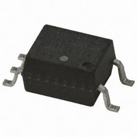
HCPL-M611 Avago Technologies US Inc., HCPL-M611 Datasheet - Page 9

HCPL-M611
Manufacturer Part Number
HCPL-M611
Description
OPTOCOUPLER LOG-OUT 10MBD 5-SOIC
Manufacturer
Avago Technologies US Inc.
Datasheet
1.HCPL-M611-000E.pdf
(11 pages)
Specifications of HCPL-M611
Voltage - Isolation
3750Vrms
Number Of Channels
1, Unidirectional
Current - Output / Channel
50mA
Data Rate
10MBd
Propagation Delay High - Low @ If
25ns @ 7.5mA
Current - Dc Forward (if)
20mA
Input Type
DC
Output Type
Open Collector
Mounting Type
Surface Mount
Package / Case
5-SOP
No. Of Channels
1
Optocoupler Output Type
Logic Gate
Input Current
15mA
Output Voltage
5.5V
Opto Case Style
SOIC
No. Of Pins
5
Propagation Delay Low-high
100ns
Isolation Voltage
3.75kV
Number Of Elements
1
Baud Rate
10Mbps
Forward Voltage
1.75V
Forward Current
20mA
Output Current
50mA
Package Type
SOIC
Operating Temp Range
-40C to 85C
Power Dissipation
85mW
Propagation Delay Time
75ns
Pin Count
5
Mounting
Surface Mount
Reverse Breakdown Voltage
5V
Operating Temperature Classification
Industrial
Lead Free Status / RoHS Status
Contains lead / RoHS non-compliant
Lead Free Status / RoHS Status
Contains lead / RoHS non-compliant, Contains lead / RoHS non-compliant
Other names
516-1081-5
Available stocks
Company
Part Number
Manufacturer
Quantity
Price
Company:
Part Number:
HCPL-M611
Manufacturer:
AGILENT
Quantity:
8 950
Part Number:
HCPL-M611
Manufacturer:
AVAGO/安华高
Quantity:
20 000
Company:
Part Number:
HCPL-M611#000E
Manufacturer:
AVAGO
Quantity:
30 000
Company:
Part Number:
HCPL-M611#500
Manufacturer:
AGILENT
Quantity:
4 020
Company:
Part Number:
HCPL-M611#500
Manufacturer:
AGILENT
Quantity:
4 028
Part Number:
HCPL-M611#500
Manufacturer:
HP
Quantity:
20 000
Company:
Part Number:
HCPL-M611#500E
Manufacturer:
AVAGO
Quantity:
30 000
Part Number:
HCPL-M611-500E
Manufacturer:
AVAGO/安华高
Quantity:
20 000
Figure 7. Propagation Delay vs. Temperature.
Figure 10. Rise and Fall Time vs. Temperature.
Figure 12. Temperature Coefficient for Forward Voltage
vs. Input Current.
9
100
300
290
80
60
40
20
60
40
20
0
0
-60
-2.4
-2.2
-2.0
-1.8
-1.6
-1.4
-1.2
-60
t
V
I
PHL
0.1
F
V
I
F
CC
-40
CC
-40
= 7.5 mA
I
= 7.5 mA
F
t
= 5.0 V
, R
T
PLH
T
– PULSE INPUT CURRENT – mA
= 5.0 V
A
A
-20
-20
L
– TEMPERATURE – °C
– TEMPERATURE – °C
= 350 Ω
, R
R
R
R
R
1 KΩ
4 KΩ
L
L
L
L
0
L
0
1
t
= 350 Ω
PLH
= 4 kΩ
= 1 kΩ
= 350 Ω
= 350 Ω, 1 kΩ, 4 kΩ
20
20
, R
t
PLH
40
L
40
= 1 KΩ
, R
10
60
60
L
= 4 KΩ
t
t
RISE
FALL
80
80
100
100
100
Figure 8. Propagation Delay vs. Pulse Input Current.
Figure 11. Test Circuit for Common Mode Transient Immunity and Typical Waveforms.
I F
105
90
75
60
45
30
V
5
FF
t
V
I
PHL
V
T
F
CM
V
V
A
CC
– PULSE INPUT CURRENT – mA
O
O
0.5 V
= 25°C
0 V
5 V
, R
= 5.0 V
7
B
A
t
L
PLH
= 350 Ω
SWITCH AT B: I
SWITCH AT A: I
1 KΩ
4 KΩ
, R
9
1
3
L
= 350 Ω
t
t
PLH
PLH
GENERATOR
11
Z
, R
, R
+
PULSE
O
= 50 Ω
L
L
F
F
= 1 KΩ
= 4 KΩ
13
= 7.5 mA
= 0 mA
_
GND
V
CC
V
V
V
CM
O
O
15
(MIN.)
(MAX.)
6
5
4
(PEAK)
Figure 9. Pulse Width Distortion vs. Temperature.
0.1 μF
BYPASS
-10
30
20
10
40
0
-60
-40
CM
CM
350 Ω
R
T
R
A
H
L
-20
L
L
= 350 kΩ
– TEMPERATURE – °C
OUTPUT V
MONITORING
NODE
= 4 kΩ
+5 V
0
R
20
L
= 1 kΩ
O
40
V
I
F
CC
60
= 7.5 mA
= 5.0 V
80
100


