4165100-XX Digital View Inc, 4165100-XX Datasheet - Page 19
4165100-XX
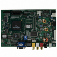
Manufacturer Part Number
4165100-XX
Description
CTRLR SVP-1280 VGA-SXGA PNLS
Manufacturer
Digital View Inc
Datasheet
1.4165100-XX.pdf
(25 pages)
Specifications of 4165100-XX
Voltage - Input
12V
Voltage - Output
3.3V, 5V, 12V
Size / Dimension
7" L x 4.74" W (179mm x 120.4mm)
Power (watts)
10W
Operating Temperature
0°C ~ 60°C
Lead Free Status / RoHS Status
Contains lead / RoHS non-compliant
Other names
586-1004


USING THE CONTROLLER WITHOUT BUTTONS ATTACHED
This is very straightforward:
•
•
•
•
Summary: On CNC1 the only pins that are used are for On/Off and Brightness (if controller mounted inverter is used). On
CNC1 the pins are for momentary type buttons so it doesn’t matter that no buttons are attached.
INVERTER CONNECTION
There are potentially 3 issues to consider with inverter connection:
•
•
•
Please read the following sections for a guide to these issues.
Inverter Power: As per the table for CNB1 pin 1 is ground and pin 2 provides 12V DC. This should be matched with the inverter
specification: see table.
Remark: For higher power inverter, more current (for 12V) can be taken from CNA1 pin 1.
Enable: This is a pin provided on some inverters for On/Off function and is used by this panel controller for VESA DPMS
compliance. If the inverter does not have an enable pin or the enable pin is not used then DPMS will not be operational. Pin 3
should be matched to the inverters specification for the ‘enable’ or ‘disable’ pin.
Further, jumpers JB2 & JB3 should be set to match the inverters specification for the enable pin power and High or Low setting:
see table.
Brightness: There are various methods for brightness control and it is important to consider the specifications for the inverter to
be used. Generally the situation is:
•
•
•
CNB1 pins 4 & 5 are available for connecting to an inverter or circuit where VR control is supported.
This can then be matched with function controls connected to CNC1 pins 4 & 3 or 5: see table.
APPLICATION NOTES
Firstly setup the controller/display system with the buttons. With controls attached and display system active make any
settings for colour, tint and image position as required then switch everything off.
Remove the control switches, the 12-way (CNC1) cable.
Use a jumper or similar to connect pins 1 & 2 on CNC1, this will fix the board On.
Refer to inverter specifications for details as to fixing brightness to a desired level, this may require a resistor, an open
circuit or closed circuit depending on inverter.
Power
Enable
Brightness
CNB1
CNB1
Brightness can controlled by using a resistor or VR (Variable Resistor).
Brightness controlled by adding a circuit such as PWM (Pulse Width Modulation).
No adjustment of brightness is possible.
CNB1
CNC1
PIN
PIN
JB2
JB3
PIN
PIN
Ref
1
2
3
4
5
3
4
5
Inverter enable voltage
Inverter control
DESCRIPTION
DESCRIPTION
DESCRIPTION
DESCRIPTION
+12VDC
Purpose
VR WIP
VR WIP
Ground
Enable
VR A
VR A
VR B
1-2 H = 12V, 2-3 H = 5V (Vcc), OPEN H = open collector
1-2 H = On, 2-3 L = On
19
Note
Related parts for 4165100-XX
Image
Part Number
Description
Manufacturer
Datasheet
Request
R

Part Number:
Description:
POST BIND STRIP 5 1/2"L F-GLASS
Manufacturer:
Keystone Electronics
Datasheet:

Part Number:
Description:
KIT OSD BRD W CBL DIGITAL POT
Manufacturer:
Digital View Inc
Datasheet:

Part Number:
Description:
Display Modules & Development Tools OSD DIGITAL I/F BRD 300MM CABLE
Manufacturer:
Digital View Inc
Datasheet:
Part Number:
Description:
Display Modules & Development Tools Digital OSD Kit
Manufacturer:
Digital View Inc
Datasheet:
Part Number:
Description:
Audio DSPs M3-310 Player w/LVDS & TTL Output
Manufacturer:
Digital View Inc


Part Number:
Description:
CABLE LVDS PANEL 460MM ROHS
Manufacturer:
Digital View Inc
Datasheet:
Part Number:
Description:
Audio DSPs M3-310 Player w/LVDS & TTL Output
Manufacturer:
Digital View Inc

Part Number:
Description:
BOARD PC/DVI INTERFACE ALR-1400
Manufacturer:
Digital View Inc

Part Number:
Description:
CTLR DVI-2560 DUAL LINK DVI 24V
Manufacturer:
Digital View Inc