HSME-C120 Avago Technologies US Inc., HSME-C120 Datasheet
HSME-C120
Specifications of HSME-C120
Available stocks


Related parts for HSME-C120


HSME-C120 Summary of contents
Page 1
... These packages are compatible with reflow soldering process. CAUTION: HSME-Cxxx LEDs are Class 1A ESD sensitive per JESD22-A114C.01. Please observe appropriate precautions during handling and processing. Refer to Application Note AN-1142 for additional details. Avago reserves the right to alter prices, specification, features, capabilities, functions, release dates, and remove availability of the product(s) at anytime. ...
Page 2
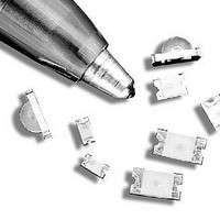
Package Dimensions CATHODE LINE LED DIE 2.6 (0.102 ) 3.2 (0.126 ) CLEAR EPOXY PC BOARD 1.6 (0.063 ) 3.2 (0.126 ) 0.8 (0.031) CATHODE LINE SOLDERING TERMINAL HSMx-C110 CATHODE MARK 1.6 (0.063 ) 1.0 (0.039) 0.3 (0.012) DIFFUSED EPOXY ...
Page 3
Package Dimensions, continued 3.2 (0.126 ) DIFFUSED 2.0 (0.079) EPOXY 0.6 (0.024) PC BOARD CATHODE LINE 0.5 ± 0.2 (0.020 ± 0.008) SOLDERING TERMINAL HSMx-C150 CATHODE MARK 0.80 (0.031) 1.60 (0.063) DIFFUSED EPOXY 0.40 (0.016) PC BOARD 0.16 (0.006) 0.30 ...
Page 4
Package Dimensions, continued CATHODE MARK 2.00 (0.079) DIFFUSED EPOXY PC BOARD 0.16 (0.006) (0.016 ± 0.006) CATHODE LINE 1.10 (0.043) SOLDERING TERMINAL HSMx-C177 Notes: 1. All dimensions in millimeters (inches). 2. Tolerance is ± 0.1 mm (± 0.004 In.) unless ...
Page 5
... Part Number HSME-C110/120 HSME-C150/170/177/190/191/197 HSME-C265 AlInGaP Green Package Description HSME-C191 Untinted, Diffused HSME-C197 Untinted, Diffused HSME-C190 Untinted, Diffused HSME-C170 Untinted, Diffused HSME-C177 Untinted, Diffused HSME-C120 Untinted, Non-diffused HSME-C110 Untinted, Non-diffused HSME-C150 Untinted, Diffused HSME-C265 Untinted, Non-diffused HSME-C110/120/170/177/ 190/191/197/150/265 –40 to +85 –40 to +85 See reflow soldering profile (Figures 6 & ...
Page 6
... Optical Characteristics 25°C A Luminous Intensity I (mcd Part Number Min. HSME-C110 18 HSME-C120 18 HSME-150/170/ 18 190/191 HSME-C177/197 18 HSME-C265 18 Notes: 1. The luminous intensity measured at the peak of the spatial radiation pattern, which may not be aligned with the mechanical axis of the lamp V package. 2. The dominant wavelength, λ ...
Page 7
... Figure 2. Forward current vs. forward voltage. HSME-C110 fig 2 100 100 -90 -80 -70 -60 -50 -40 -30 Figure 5a. Relative intensity vs. angle for HSMx-C170, HSMx-C190, HSMx-C191, and HSMx-C150 1.2 1.0 0.8 0.6 0.4 0 2.0 2.1 2.2 I – FORWARD CURRENT – Figure 3. Luminous intensity vs. forward current. HSME-C110 fig 3 -20 - ANGLE HSME-C110 fig ...
Page 8
... HSME-C110 fig 5c -100 -80 -60 -40 -20 ANGLE Figure 5c. Relative intensity vs. angle for HSMx-C110. HSME-C110 fig 5c-2 100 -90 -80 -70 -60 -50 -40 -30 -20 -10 ANGLE 100 90 HSME-C110 fig 5d -90 -80 -70 -60 -50 -40 -30 -20 -10 0 ANGLE Figure 5d. Relative intensity vs. angle for HSMx-C120. HSME-C110 fig 5d 100 100 ...
Page 9
... DIA. PCB HOLE 1.25 (0.049) 2.3 1.4 (0.091) (0.055) 5.0 (0.200) 0.9 (0.035) 1.0 (0.039) CENTERING BOARD 1.5 2.0 1.5 (0.059) (0.079) (0.059) HSME-C110 fig 9 1.5 2.0 1.5 (0.059) (0.079) (0.059) Figure 13. Recommended soldering pattern for HSMx-C150. HSME-C110 fig 12 –3°C/SEC. 1.5 (0.059) ...
Page 10
USER FEED DIRECTION PRINTED LABEL Figure 14. Reeling orientation. 3.0 ± 0.5 (0.118 ± 0.020) 178.40 ± 1.00 (7.024 ± 0.039) 4.0 ± 0.5 (0.157 ± 0.020) Figure 15. Reel dimensions. Note: 1. All dimensions in millimeters (inches). CATHODE SIDE ...
Page 11
DIM. A (SEE TABLE 1) DIM. B (SEE TABLE 1) 2.00 ± 0.05 (0.079 ± 0.002) 4.00 (0.157) HSMx-C110/C120 POSITION IN CARRIER TAPE DIM. A (SEE TABLE 1) DIM. B (SEE TABLE 1) 4.00 (0.157) DIM. A (SEE ...
Page 12
END THERE SHALL BE A MOUNTED WITH COMPONENTS MINIMUM OF 160 mm (6.3 INCH) OF EMPTY COMPONENT POCKETS SEALED WITH COVER TAPE. Figure 17. Tape leader and trailer dimensions. For product information and a complete list of distributors, please go ...