TLHR6200 Vishay, TLHR6200 Datasheet - Page 3
TLHR6200
Manufacturer Part Number
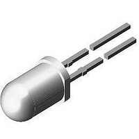
TLHR6200
Description
LED 5MM RED 20MCD GAASP ON GAP
Manufacturer
Vishay
Datasheet
1.TLHR6205.pdf
(9 pages)
Specifications of TLHR6200
Color
Red
Millicandela Rating
20mcd
Current - Test
10mA
Wavelength - Dominant
618.5nm
Wavelength - Peak
635nm
Voltage - Forward (vf) Typ
2V
Lens Type
Clear, Red Tinted
Lens Style/size
Round, 5mm, T-1 3/4
Package / Case
Radial - 2 Lead
Height
8.70mm
Viewing Angle
28°
Mounting Type
Through Hole
Resistance Tolerance
618.5nm
Led Size
T-1 3/4
Illumination Color
Red
Lens Color/style
Tinted, Non-Diffused
Operating Voltage
2 V
Wavelength
618.5 nm
Luminous Intensity
50 mcd
Operating Current
10 mA
Lens Dimensions
5 mm x 5 mm x 7.7 mm
Lens Shape
Dome
Maximum Operating Temperature
+ 100 C
Minimum Operating Temperature
- 20 C
Mounting Style
Through Hole
Lead Free Status / RoHS Status
Lead free / RoHS Compliant
Luminous Flux @ Current - Test
-
Lead Free Status / RoHS Status
Lead free / RoHS Compliant, Lead free / RoHS Compliant
Other names
751-1136


Note:
1)
2)
TYPICAL CHARACTERISTICS
T
Document Number 83218
Rev. 1.7, 04-Aug-09
amb
OPTICAL AND ELECTRICAL CHARACTERISTICS
PARAMETER
Luminous intensity
Dominant wavelength
Peak wavelength
Angle of half intensity
Forward voltage
Reverse voltage
Junction capacitance
T
In one packing unit I
amb
= 25 °C, unless otherwise specified
Figure 1. Forward Current vs. Ambient Temperature
= 25 °C, unless otherwise specified
95 10025
95 10046
10 000
1000
Figure 2. Forward Current vs. Pulse Length
100
10
60
50
40
30
20
10
1
0
0.01
0
t
T
p
/T = 0.01
amb
2)
1
Vmin.
20
t
- Ambient Temperature (°C)
p
0.1
- Pulse Length (ms)
/I
0.5
Vmax.
40
0.02
≤ 0.5
1
0.2
60
0.05
T
amb
TEST CONDITION
V
R
10
For technical support, please contact:
≤
80
I
I
I
I
I
= 0, f = 1 MHz
I
F
F
F
F
F
85 °C
R
= 10 mA
= 10 mA
= 10 mA
= 10 mA
= 20 mA
= 10 µA
0.1
100
100
TLHG6200
PART
TLHG620., TLHR620., TLHY620.
1)
Figure 3. Rel. Luminous Intensity vs. Angular Displacement
TLHG620., GREEN
SYMBOL
LED@vishay.com
V
95 10044
V
λ
λ
I
C
95 10026
ϕ
V
R
Figure 4. Forward Current vs. Forward Voltage
d
p
F
j
1000
100
0.1
1.0
0.9
0.8
0.7
10
1
0
0.6
red
MIN.
562
16
6
0.4
V
2
F
- Forward Voltage (V)
Vishay Semiconductors
0.2
4
TYP.
± 14
565
2.4
0
0°
40
15
50
6
0.2
10°
t
p
t
/T = 0.001
p
= 10 µs
0.4
8
MAX.
20°
575
3
0.6
www.vishay.com
10
30°
40°
50°
60°
70°
80°
UNIT
mcd
deg
nm
nm
pF
V
V
3
Related parts for TLHR6200
Image
Part Number
Description
Manufacturer
Datasheet
Request
R

Part Number:
Description:
357-036-542-201 CARDEDGE 36POS DL .156 BLK LOPRO
Manufacturer:
Vishay
Datasheet:
Part Number:
Description:
357-036-542-201 CARDEDGE 36POS DL .156 BLK LOPRO
Manufacturer:
Vishay
Datasheet:
Part Number:
Description:
357-036-542-201 CARDEDGE 36POS DL .156 BLK LOPRO
Manufacturer:
Vishay
Datasheet:
Part Number:
Description:
357-036-542-201 CARDEDGE 36POS DL .156 BLK LOPRO
Manufacturer:
Vishay
Datasheet:
Part Number:
Description:
357-036-542-201 CARDEDGE 36POS DL .156 BLK LOPRO
Manufacturer:
Vishay
Datasheet:
Part Number:
Description:
357-036-542-201 CARDEDGE 36POS DL .156 BLK LOPRO
Manufacturer:
Vishay
Datasheet:
Part Number:
Description:
357-036-542-201 CARDEDGE 36POS DL .156 BLK LOPRO
Manufacturer:
Vishay
Datasheet:
Part Number:
Description:
357-036-542-201 CARDEDGE 36POS DL .156 BLK LOPRO
Manufacturer:
Vishay
Datasheet:
Part Number:
Description:
357-036-542-201 CARDEDGE 36POS DL .156 BLK LOPRO
Manufacturer:
Vishay
Datasheet:
Part Number:
Description:
357-036-542-201 CARDEDGE 36POS DL .156 BLK LOPRO
Manufacturer:
Vishay
Datasheet:
Part Number:
Description:
357-036-542-201 CARDEDGE 36POS DL .156 BLK LOPRO
Manufacturer:
Vishay
Datasheet:
Part Number:
Description:
357-036-542-201 CARDEDGE 36POS DL .156 BLK LOPRO
Manufacturer:
Vishay
Datasheet:
Part Number:
Description:
357-036-542-201 CARDEDGE 36POS DL .156 BLK LOPRO
Manufacturer:
Vishay
Datasheet:
Part Number:
Description:
357-036-542-201 CARDEDGE 36POS DL .156 BLK LOPRO
Manufacturer:
Vishay
Datasheet:
Part Number:
Description:
357-036-542-201 CARDEDGE 36POS DL .156 BLK LOPRO
Manufacturer:
Vishay
Datasheet: