HSMC-S670 Avago Technologies US Inc., HSMC-S670 Datasheet
HSMC-S670
Specifications of HSMC-S670
Available stocks


Related parts for HSMC-S670


HSMC-S670 Summary of contents
Page 1
... HSMx-S660 Series HSMx-S670 Series HSMx-S690 Series applications. The HSMx-S660 right angle, 3.0 x 2.0 x 1.0 mm LED is optimum for side lighting applications where direct back- lighting is not practical. All packages are compatible with IR and convective reflow solder- ing processes. Red 626 nm HSMC-S690 HSMC-S670 HSMC-S660 ...
Page 2
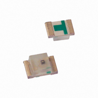
Package Dimensions 1.25 (0.13) 2.0 1.3 1 CATHODE MARK HSMx-S670 Series 0.3 FRONT VIEW R0.8 3 TOP VIEW 0.25 CATHODE PIN CONNECTION MARK REAR VIEW HSMx-S660 Series Absolute Maximum Ratings at T Parameter [1][2][3][4] DC Forward Current Power ...
Page 3
... Electrical Characteristics at T Part Number Color HSMA-S660 Amber HSMA-S670 Amber HSMA-S690 Amber HSMD-S660 Orange HSMD-S670 Orange HSMD-S690 Orange HSMC-S660 Red HSMC-S670 Red HSMC-S690 Red = 25ºC A Luminous Intensity I Peak Dominant V = Wavelength Wavelength F [ (nm) peak Typ ...
Page 4
Yellow/Amber Color Bins Bin ID Min. A 582.0 B 584.5 C 587.0 D 589.5 E 592.0 F 594.5 Tolerance: 0.5 nm. Orange Color Bins Dom. Wavelength (nm) Bin ID Min. A 597.0 B 600.0 C 603.0 D 606.0 E 609.0 ...
Page 5
Light Intensity (Iv) Bin Limits Bin ID Min. A 0.11 B 0.18 C 0.29 D 0.45 E 0.72 F 1.10 G 1.80 H 2.80 J 4.50 K 7.20 L 11.20 M 18.00 N 28.50 P 45.00 Q 71.50 R 112.50 ...
Page 6
AMBER 0.5 0 550 594 600 607 WAVELENGTH – nm Figure 1. Relative Intensity vs. Wavelength. 100 0.5 0 0.5 1.0 1.5 2.0 2.5 3.0 3.5 V – FORWARD VOLTAGE – ...
Page 7
ANGULAR DISPLACEMENT – DEGREES Figure 5. Relative Luminous Intensity vs. Angular Displacement for HSMx-S660. 1.0 0.9 0.8 0.7 0.6 0.5 0.4 0.3 0.2 0.1 ...
Page 8
RWS CENTER 1.5 MOUNTING EXAMPLE EMITTED DIRECTION HSMX-S660 SERIES Figure 8. Recommended Solder Patterns. 255 °C (+5/-0) 217 °C 3 °C/SEC. MAX. 140 - 160 °C MAX. 120 SEC. TIME * THE TIME FROM 25 ...
Page 9
USER FEED DIRECTION PRINTED LABEL Figure 10. Reeling Orientation. 4.00 ± 0.10 (0.157 ± 0.004) DIM. A (SEE TABLE 1) DIM. B (SEE TABLE 1) 2.00 ± 0.05 (0.079 ± 0.002) 4.00 ± 0.10 (0.157 ± 0.004) Figure 12. Tape ...
Page 10
CATHODE 4.00 ± 0.10 HOLE (0.157 ± 0.004) 2.00 ± 0.05 (0.079 ± 0.002) Figure 13. Tape Dimensions HSMx-S660. END THERE SHALL BE A MOUNTED WITH MINIMUM OF ...
Page 11
For product information and a complete list of distributors, please go to our web site. For technical assistance call: Americas/Canada: +1 (800) 235-0312 or (916) 788-6763 Europe: +49 (0) 6441 92460 China: 10800 650 0017 Hong Kong: (+65) 6756 ...