ASMT-JH30-ARS01 Avago Technologies US Inc., ASMT-JH30-ARS01 Datasheet
ASMT-JH30-ARS01
Specifications of ASMT-JH30-ARS01
Available stocks


Related parts for ASMT-JH30-ARS01


ASMT-JH30-ARS01 Summary of contents
Page 1
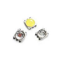
... ASMT-Jx3x 3W Mini Power LED Light Source Data Sheet Description The 3W Mini Power LED Light Source is a high perfor- mance energy efficient device which can handle high thermal and high driving current. Option with electrically isolated metal slug is also available. The White Mini Power LED is available in the range of color temperature from 2700K to 10000K ...
Page 2
... Package Dimensions 5.0 4.0 Metal Slug 0.65 0.60 Figure 1. ASMT-Jx3x package outline drawing Notes: 1. All dimensions in millimeters. 2. Metal slug is connected to anode for electrically non-isolated option. 3. Tolerance is ±0.1 mm unless otherwise specified. 4. Terminal finish: Ag plating. 5. Corresponding NC (No Connection) leads adjacent to anode and cathode leads can be electrically short. ...
Page 3
... Note: 1. Please refer to Page 10 for selection details. Device Selection Guide (T = 25°C) J Part Number Color ASMT-JD30-ALN01 Deep Red ASMT-JR30-ARS01 Red ASMT-JH30-ARS01 Red Orange ASMT-JA30-ARS01 Amber ASMT-JG31-NTU01 Green ASMT-JB31-NMP01 Blue ASMT-JL31-NPQ01 Royal Blue ASMT-JW31-NTV01 Cool White ASMT-JW31-NUV01 ASMT-JN31-NTV01 Neutral White ASMT-JN31-NUV01 ASMT-JY31-NSU01 ...
Page 4
... Derate linearly based on Figure 9 for AlInGaP and Figure 21 for InGaN. 2. Pulse condition duty factor = 10%, Frequency = 1 kHz. 3. Not designed for reverse bias operation. Optical Characteristics at 350 25°C) J Part Number Color ASMT-JD30-ALN01 Deep Red ASMT-JR30-ARS01 Red ASMT-JH30-ARS01 Red Orange ASMT-JA30-ARS01 Amber ASMT-JG31-NTU01 Green ASMT-JB31-NMP01 Blue ASMT-JL31-NPQ01 Royal Blue Part Number Color ...
Page 5
... InGaN 2.8 Note Thermal Resistance from LED junction to metal slug. j-ms Optical and Electrical Characteristic at 700 mA (T Part Number Color ASMT-JD30-ALN01 Deep Red ASMT-JR30-ARS01 Red ASMT-JH30-ARS01 Red Orange ASMT-JA30-ARS01 Amber ASMT-JG31-NTU01 Green ASMT-JB31-NMP01 Blue ASMT-JL31-NPQ01 Royal Blue ASMT-JW31-NTV01 Cool White ASMT-JW31-NUV01 ...
Page 6
AlInGaP 1 0.9 AMBER 0.8 RED ORANGE 0.7 RED DEEP RED 0.6 0.5 0.4 0.3 0.2 0.1 0 520 535 550 565 580 595 610 625 640 655 670 685 700 WAVELENGTH - nm Figure 2. Relative Intensity vs. Wavelength ...
Page 7
DEEP RED RED 40.0 RED-ORANGE 20.0 AMBER 0.0 -50 - JUNCTION TEMPERATURE,T Figure 8. Relative Light Output vs. Junction Temperature. 800 700 600 500 400 RT = 20°C/W ...
Page 8
InGaN 1.0 0.9 0.8 0.7 0.6 0.5 0.4 0.3 0.2 0.1 0.0 380 430 480 530 580 WAVELENGTH - nm Figure 12. Relative Intensity vs. Wavelength for Cool and Warm White. 2 1.8 1.6 1.4 1.2 1 0.8 0.6 0.4 ...
Page 9
PULSE DURATION sec Figure 18. Maximum pulse current vs. ambient temperature. Derated based 25° 30°C/W A J-A 120.0 110.0 100.0 ...
Page 10
Solder Pad Slug Indepdent 1.32 Solder Pad Figure 24. Recommended soldering land pattern 255 - 260°C 3°C/SEC. MAX. 217°C 200°C 150°C 3°C/SEC. MAX 120 SEC. TIME Figure 26. Recommended Reflow Soldering Profile Note: For detail information on ...
Page 11
... Option Selection Details ASMT – – Minimum Flux Bin Selection 4 x – Maximum Flux Bin Selection 5 x – Color Bin Selection 6 x – Packaging Option 7 Color Bin Selection ( Individual reel will contain parts from one color bin selection only. Cool White ...
Page 12
VM 6300K 0. 7000K 0. 0.32 WP 10000K 0.30 YA 0.28 0.26 0.26 0.28 0.30 0.32 0.34 X-COORDINATE Figure 27. Color bin Structure for ...
Page 13
Color Bin Limits Cool Color Limits White (Chromaticity Coordinates) Bin UM x 0.365 0.367 y 0.386 0.400 Bin UN x 0.365 0.362 y 0.386 0.372 Bin U0 x 0.362 0.360 y 0.372 0.357 Bin UP x 0.360 0.357 y 0.357 ...
Page 14
... Tolerance: ±1 nm 0.362 0.365 0.372 0.386 0.360 0.362 0.357 0.372 0.357 0.360 Color 0.342 0.357 Deep Red Royal Blue Tolerance: ±2 nm Example ASMT-JG31-NST01 ASMT-JG31-Nxxxx – Green, InGaN, Electrically isolated Dominant Wavelength (nm) at 350 mA Bin ID Min. Max. – 620.0 635.0 – ...
Page 15
Tape and Reel – Option 1 4.00 ±.10 8.00 ±.10 8° 4.15 ±.10 Figure 30. Carrier Tape Dimensions 3 ±0.5 ø10 178 ±1 4 ±0.5 Notes: 1. Empty component pockets sealed with top cover tape. 2. 250 or 500 pieces ...
Page 16
USER FEED DIRECTION PRINTED LABEL Figure 32. Reeling Orientation DISCLAIMER: Avago’s products and software are not specifically designed, manufactured or authorized for sale as parts, components or assemblies for the planning, construction, maintenance or direct operation of a nuclear facility ...