BP5220A Rohm Semiconductor, BP5220A Datasheet
BP5220A
Specifications of BP5220A
Available stocks


Related parts for BP5220A


BP5220A Summary of contents
Page 1
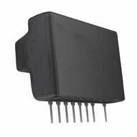
... Step-down DC/DC Converters(Non-isolated) BP5220A / BP5221A / BP5222A Description The BP5220A, BP5221A, BP5222A, are converters that use a pulse width modulation (PWM) system. They contain control circuits, switching devices, rectifiers, and coils, and operate by only connecting smoothing capacitor. With a high efficiency of power conversion, the modules are available in stand-alone 9-pin SIP packages with no heat sink required ...
Page 2
... BP5220A/BP5221A/BP5222A Block diagram BP5220A / BP5221A / BP5222A POWER SUPPLY CIRCUIT 9 Vi Electrical characteristics BP5220A (Unless otherwise noted : Vi=15V, Io=0.5A, SW=1, Ta=25˚C) Parameter Symbol Input voltage Vi Output voltage V Output current Line regulation Load regulation Output ripple voltage Power conversion efficiency f Switching frequency ...
Page 3
... ROHM Co., Ltd. All rights reserved. Min. Typ. Max. Unit 11 190 kHz SW 4.7 ON 200 OFF BP5220A / BP5221A / BP5222A Frequency counter Fig.1 T 3/7 Data Sheet Conditions Vi=15V to 38V Io=0.05A to 0.5A Io=0.5A Vo>11.2V Vo<0.1V, SW=2 Output Switching frequency=1/T Output ripple voltage 2010.03 - Rev. B ...
Page 4
... Be sure to use fuse for safety 120pF BP5220A / BP5221A / BP5222A 100 OFF 100k 2SC1740 Fig.6 4/7 Data Sheet BP5220A / BP5221A / BP5222A Fig.2 BP5220A / BP5221A / BP5222A Output OFF Fig 24V 0.2 0.4 0.6 0.8 1.0 1.2 OUTPUT CURRENT (A) Fig 470 F 2010.03 - Rev. B ...
Page 5
... When the output voltage is increased by 20%, for instance, the minimum input voltage is also increased by 20%. (Example : When the output voltage is changed from the BP5220A, the minimum input voltage is charged from 8V to 9.6V) Application Example 4 : Slow start The slow start circuit mitigates the pulse load on the internal switching transistor when input voltage is applied, and increases the output voltage gradually by starting the switching operation slowly ...
Page 6
... A smoothing electrolytic capacitor is necessary for I/O external components. Please use a capacitor equivalent to the recommended one. (6) Please put an I/O smoothing capacitor near the module. Output ripple voltage may be larger or output voltage may not be stable. Electrical Characteristics Curves BP5220A 1200 1000 Vi=8 to 15V Vi=34V ...
Page 7
... ROHM Co., Ltd. All rights reserved. 100 Vi=23V 80 Vi=38V Vi=30V 120 0 0.1 0.2 0.3 0.4 0.5 OUTPUT CURRENT : I (A) O Fig.17 Efficiency BP5220A / BP5221A / BP5222A Voltage difference between pins 2 and 9 Fig.19 ASO measurement circuit 7/7 Data Sheet 10 Pw=1ms 4.5A 2.2A Pw=10ms 1 Tc=25 ° ...
Page 8
...
Page 9
No copying or reproduction of this document, in part or in whole, is permitted without the consent of ROHM Co.,Ltd. The content specified herein is subject to change for improvement without notice. The content specified herein is for the purpose ...