FPS100048 TDK Corporation, FPS100048 Datasheet - Page 40
FPS100048
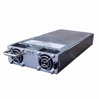
Manufacturer Part Number
FPS100048
Description
PWR SUP FNT END 48V 1008W 21A
Manufacturer
TDK Corporation
Series
FPSr
Type
Commercialr
Datasheets
1.FPS100024.pdf
(57 pages)
2.FPS100024.pdf
(2 pages)
3.FPS100024.pdf
(1 pages)
4.FPS100048.pdf
(3 pages)
5.FPS100048.pdf
(4 pages)
Specifications of FPS100048
Power Supply Type
Switching (Closed Frame)
Voltage - Output
48V
Number Of Outputs
1
Power (watts)
1000W
Applications
Commercial
Voltage - Input
85 ~ 265VAC
Mounting Type
Chassis Mount
1st Output
48 VDC @ 21A
Size / Dimension
1.61" L x 5" W x 11.4" H (40.9mm x 127mm x 289.6mm)
Power (watts) - Rated
1008W
Operating Temperature
0°C ~ 70°C
Efficiency
88%
Approvals
CE, EN, UL
Line Regulation
0.4%
Load Regulation
0.8%
Power Supply Output Type
Fixed
No. Of Outputs
1
Output Voltage
48V
Output Current
21A
Power Rating
1kW
Input Voltage
85V AC To 265V AC / 120V DC To 360V DC
Maximum Output Current
21 A
Maximum Output Power
1008 W
Input Frequency
47 to 63 Hz
Brand/series
FPS1000 Series
Configuration
Enclosed
Operation
Linear
Output
48 VDC @ 21 A
Power, Output
1008 W
Primary Type
AC-DC
Special Features
High Efficiency, Hot Swappable, PFC, Remote On/Off, Remote Sense
Voltage, Input
85 to 265/120 to 360 VAC/VDC
Voltage, Output
48 VDC
Output Current (max)
21A
Screening Level
Commercial
Product Depth (mm)
127mm
Operating Temperature Min Deg. C
0C
Operating Temperature Max Deg. C
70C
Mounting Style
Screw
Lead Free Status / RoHS Status
Lead free / RoHS Compliant
3rd Output
-
2nd Output
-
4th Output
-
Lead Free Status / Rohs Status
RoHS Compliant part
Other names
285-1239
Available stocks
Company
Part Number
Manufacturer
Quantity
Price
Company:

Part Number:
FPS100048/PS
Manufacturer:
TDK-LAMBDA
Quantity:
232


CHAPTER 14
14.1 Introduction
The FPS-S1U rack provides access to the I
panel DB25 female connector located at the rear panel. The Clock is connected to pin 20 and the Data
is connected to pin 21. The specifications of the I
are installed in the FPS-S1U rack. Refer to Chapter 7 for the specifications and all operating details.
14.2 Addressing (A0, A1, A2).
The rear panel 9 positions DIP switch is used to select the I
unit inside the rack. Each unit should have its own I
Each address is made of three DIP switch positions, thus a single power supply in the FPS-S1U can be
addressed with one of 8 different addresses.
Refer to Fig 14-1 for the description of the DIP switch setting. The DIP switch down position is logic level
"1" and the up position is logic level "0".
FPS-S1U I
Fig 14-1: Address setting DIP switch (rear panel view)
The I
referenced to the -Sense potential. When using series
connection of FPS-S1U racks, do not connect the
1
Module C
2
C bus address lines, serial clock and data are
2
2
C BUS INTERFACE OPTION
I
2
3
C lines of the units together.
4
2
C Bus interface in each installed FPS1000/S unit via the rear
Module B
CAUTION
5
2
C of the FPS1000/S power supplies are kept when they
37
2
C address to communicate over the I
6
7
2
Module A
C bus address for the individual FPS1000/S
8
9
FPS-S1U Instruction Manual
ON
OFF
2
C bus.
Related parts for FPS100048
Image
Part Number
Description
Manufacturer
Datasheet
Request
R

Part Number:
Description:
TDK DC to DC Converters, DC to AC Inverters
Manufacturer:
TDK Corporation
Datasheet:
Part Number:
Description:
TDK DC to DC Converters, DC to AC Inverters
Manufacturer:
TDK Corporation
Datasheet: