PL-USB-BLASTER-RCN Altera, PL-USB-BLASTER-RCN Datasheet
PL-USB-BLASTER-RCN
Specifications of PL-USB-BLASTER-RCN
PL-USB-BLTER-RCN-OB
Available stocks


Related parts for PL-USB-BLASTER-RCN


PL-USB-BLASTER-RCN Summary of contents
Page 1
... Innovation Drive San Jose, CA 95134 www.altera.com UG-USB81204-2.5 P25-10325-03 USB-Blaster Download Cable Software Version: Document Version: Document Date: User Guide 9.0 2.5 © April 2009 ...
Page 2
... Altera warrants performance of its semiconductor products to current specifications in accordance with Altera's standard warranty, but reserves the right to make changes to any products and services at any time without notice. Altera assumes no responsibility or liability arising out of the application or use of any information, product, or service described herein except as expressly agreed to in writing by Altera Corporation ...
Page 3
... Voltage Requirements . . . . . . . . . . . . . . . . . . . . . . . . . . . . . . . . . . . . . . . . . . . . . . . . . . . . . . . . . . . . . . . . . 2–1 Cable-to-Board Connection . . . . . . . . . . . . . . . . . . . . . . . . . . . . . . . . . . . . . . . . . . . . . . . . . . . . . . . . . . . . . 2–2 USB-Blaster Plug Connection . . . . . . . . . . . . . . . . . . . . . . . . . . . . . . . . . . . . . . . . . . . . . . . . . . . . . . . . . . . 2–3 Circuit Board Header Connection . . . . . . . . . . . . . . . . . . . . . . . . . . . . . . . . . . . . . . . . . . . . . . . . . . . . . . . 2–4 Operating Conditions . . . . . . . . . . . . . . . . . . . . . . . . . . . . . . . . . . . . . . . . . . . . . . . . . . . . . . . . . . . . . . . . . . . . 2–5 USB-Revision . . . . . . . . . . . . . . . . . . . . . . . . . . . . . . . . . . . . . . . . . . . . . . . . . . . . . . . . . . . . . . . . . . . . . . . . . . . 2–7 Statement of China-RoHS Compliance . . . . . . . . . . . . . . . . . . . . . . . . . . . . . . . . . . . . . . . . . . . . . . . . . . . . . 2–8 References . . . . . . . . . . . . . . . . . . . . . . . . . . . . . . . . . . . . . . . . . . . . . . . . . . . . . . . . . . . . . . . . . . . . . . . . . . . . . . 2–8 Additional Information . . . . . . . . . . . . . . . . . . . . . . . . . . . . . . . . . . . . . . . . . . . . . . . . . . . . . . . . . . . . . . . . . About–1 Revision History . . . . . . . . . . . . . . . . . . . . . . . . . . . . . . . . . . . . . . . . . . . . . . . . . . . . . . . . . . . . . . . . . . . About–1 How to Contact Altera . . . . . . . . . . . . . . . . . . . . . . . . . . . . . . . . . . . . . . . . . . . . . . . . . . . . . . . . . . . . . . About–2 Typographic Conventions . . . . . . . . . . . . . . . . . . . . . . . . . . . . . . . . . . . . . . . . . . . . . . . . . . . . . . . . . . . About–2 © ...
Page 4
... USB-Blaster Download Cable User Guide © April 2009 Altera Corporation ...
Page 5
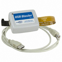
... Figure 1–1: The USB-Blaster Download Cable . . . . . . . . . . . . . . . . . . . . . . . . . . . . . . . . . . . . . . . . . . . . . . . . . . 1-3 Figure 1–2: Hardware Setup Dialog Box . . . . . . . . . . . . . . . . . . . . . . . . . . . . . . . . . . . . . . . . . . . . . . . . . . . . . . 1-6 Figure 2–1: USB-Blaster Block Diagram . . . . . . . . . . . . . . . . . . . . . . . . . . . . . . . . . . . . . . . . . . . . . . . . . . . . . . . 2-2 Figure 2–2: USB-Blaster Dimension . . . . . . . . . . . . . . . . . . . . . . . . . . . . . . . . . . . . . . . . . . . . . . . . . . . . . . . . . . . 2-3 Figure 2–3: USB-Blaster 10-Pin Female Plug Dimensions . . . . . . . . . . . . . . . . . . . . . . . . . . . . . . . . . . . . . . . . 2-3 Figure 2–4: 10-Pin Male Header Dimensions . . . . . . . . . . . . . . . . . . . . . . . . . . . . . . . . . . . . . . . . . . . . . . . . . . . 2-4 © April 2009 Altera Corporation v ...
Page 6
... USB-Blaster Download Cable User Guide List of Figures © April 2009 Altera Corporation ...
Page 7
... List of Tables Table 1–1: Programming Modes . . . . . . . . . . . . . . . . . . . . . . . . . . . . . . . . . . . . . . . . . . . . . . . . . . . . . . . . . . . . . 1-7 Table 2–1: USB-Blaster VCC(TRGT) Pin Voltage Requirements . . . . . . . . . . . . . . . . . . . . . . . . . . . . . . . . . . . 2-1 Table 2–2: USB-Blaster Female Plug Signal Names & Programming Modes . . . . . . . . . . . . . . . . . . . . . . . . 2-4 Table 2–3: USB-Blaster Cable Absolute Maximum Ratings . . . . . . . . . . . . . . . . . . . . . . . . . . . . . . . . . . . . . . . 2-5 Table 2–4: USB-Blaster Cable Recommended Operating Conditions . . . . . . . . . . . . . . . . . . . . . . . . . . . . . . 2-5 Table 2– ...
Page 8
... USB-Blaster Download Cable User Guide List of Tables © April 2009 Altera Corporation ...
Page 9
... You can use the USB-Blaster download cable to download configuration data to the following Altera devices: ® Stratix series FPGAs ■ ® ■ Cyclone ® ■ MAX series CPLDs ® ■ Arria GX series FPGAs ™ APEX series FPGAs ■ ® ACEX 1K FPGAs ■ ...
Page 10
... Software Requirements The USB-Blaster download cable is only available for Windows 2000, Windows XP (32-bit and 64-bit), Windows Vista (32-bit and 64-bit), UNIX and all Linux plaforms such as Red Hat Enterprise 4, Red Hat Enterprise 5, CentOS 4/5, and SUSE Linux Enterprise 9. 1 For Quartus operating system support, refer ...
Page 11
... To avoid damaging the USB-Blaster cable, first unplug the cable from the 10-pin header on the target board before unplugging the cable from the USB port on your PC safest to remove power first from the target board before unplugging the USB-Blaster cable. For more information, refer to Figure 1– ...
Page 12
... Select Altera USB-Blaster and click Next to continue. 8. Click Next to install the driver. 9. Click Continue Anyway when the Hardware Installation warning appears. 10. Click Finish in the Completing the Add/Remove Hardware Wizard window. Reboot your system. Installing the USB-Blaster Driver on Windows Vista Systems This section describes how to install the USB-Blaster driver on Windows Vista systems ...
Page 13
... Create a file named /etc/hotplug/usb/usbblaster and add the following lines to it. #!/bin/sh # USB-Blaster hotplug script ...
Page 14
... BUS=="usb", SYSFS{idVendor}=="09fb", SYSFS{idProduct}=="6001", MODE="0666", PROGRAM="/bin/sh -c 'K=%k; K=$${K#usbdev}; printf /proc/bus/usb/%%03i/%%03i $${K%%%%.*} $${K#*.}'", RUN+="/bin/chmod 0666 %c" 2. Complete your installation by setting up the programming hardware in the Quartus II software as described in the the Quartus II f For more information about USB-Blaster driver installation, refer to www ...
Page 15
... Programs or configures all Altera devices supported by Quartus II software, excluding FLEX 6000 and EPCS serial configuration devices. Not supported by the USB-Blaster. Configures all Altera devices supported by Quartus II software excluding MAX 3000, MAX 7000, MAX II, EPC enhanced configuration devices, and EPCS serial configuration devices. ...
Page 16
... USB-Blaster Download Cable User Guide Chapter 1: Setting Up the USB-Blaster Download Cable Software Setup © April 2009 Altera Corporation ...
Page 17
... China-RoHS Compliance” on page 2–8 USB-Blaster Connections The USB-Blaster cable has a USB universal plug that connects to the PC USB port, and a 10-pin female plug that connects to the circuit board. Data is downloaded from the USB port on the PC through the USB-Blaster cable to the circuit board via the connections discussed in this section ...
Page 18
... As specified by V CCIO 5 V 2 3.3 V 3.3 V 3.3 V USBVCC Voltage Translator Circuitry EPM7064AETC44 I/O I/Os I/O I/O I/Os I/O I/O I/O I/O I/O Chapter 2: USB-Blaster Specifications USB-Blaster Connections Figure 2–1 shows (TRGT) 10-Pin Pin 1 Female Plug © April 2009 Altera Corporation ...
Page 19
... Chapter 2: USB-Blaster Specifications USB-Blaster Connections USB-Blaster Plug Connection The 10-pin female plug connects to a 10-pin male header on the circuit board containing the target device. Figure 2–3 shows the dimension of the female plug. Figure 2–2. USB-Blaster Dimension 1.0 Note to Figure 2–2: (1) For Rev. B and Rev. C. ...
Page 20
... I/O drivers. Circuit Board Header Connection The circuit board's 10-pin male header, which connects to the USB-Blaster cable's 10-pin female plug, has two rows of five pins. These pins are connected to the device’s programming or configuration pins. 10-pin male header. ...
Page 21
... Table 2–4. USB-Blaster Cable Recommended Operating Conditions Symbol V CC(TRGT) Note to Table 2–4: (1) This operating condition can be applicable to USB-Blaster Cable (Rev. A & B) Table 2–5. USB-Blaster Cable (Rev. A & Operating Conditions Symbol V High-level input IH voltage V Low-level input IL voltage © April 2009 Altera Corporation Table 2– ...
Page 22
... V CC(TRGT 4 CC(TRGT 3 CC(TRGT 2.375 V, I CC(TRGT 1. CC(TRGT) OH Chapter 2: USB-Blaster Specifications Operating Conditions Min Max Unit 4.4 V 2.9 V 2.275 1.61 V 1.33 V 0.125 V 0.125 0.125 0.125 V 0.125 V 100 uA Min Max Unit 2 CC(TRGT) 0 - 1.2 V © April 2009 Altera Corporation ...
Page 23
... USB-Blaster through a flexible PCB cable. Hardware upgrade to meet the RoHS lead-free requirement. 10-pin female connector is connected to the USB-Blaster through a flexible PCB cable. 2–7 Min Max Unit 0 0.5 V 100 uA RoHS Compliant No No Yes USB-Blaster Download Cable User Guide ...
Page 24
... Stratix II chapter in volume 1 of the Stratix III Device Handbook chapter in the Introduction to the Quartus II Software chapter in volume 3 of the Quartus II Handbook ® II online tutorial Chapter 2: USB-Blaster Specifications Statement of China-RoHS Compliance (Note 1) Polybrominated Polybrominated diphenyl Ethers biphenyls (PBB) (PBDE) ...
Page 25
... Refer to the following procedures in the Quartus II Help: Programming a Single Device or Multiple Devices in JTAG or Passive Serial ■ Mode Programming a Single Device in Active Serial Programming Mode ■ ■ Refer to the following introduction and overview topics in the Quartus II Help: Programmer Introduction ■ ...
Page 26
... USB-Blaster Download Cable User Guide Chapter 2: USB-Blaster Specifications References © April 2009 Altera Corporation ...
Page 27
... Requirements” “Installing the USB-Blaster Driver on Windows Vista Systems” Table 2–1 “Circuit Board Header Connection” Table 2–5 “Statement of China-RoHS Compliance” Table 2–8 “Installing the USB-Blaster Driver on Windows Vista Systems” “Introduction” “Installing the USB-Blaster Driver on Linux” ...
Page 28
... Examples \qdesigns directory, d: drive, chiptrip.gdf file. MAX Document titles are shown in italic type with initial capital letters. Example: AN 75: High-Speed Board Design. Internal timing parameters and variables are shown in italic type. Examples ...
Page 29
... Typographic Conventions Visual Cue © April 2009 Altera Corporation Meaning A caution calls attention to a condition or possible situation that can damage or destroy the product or the user’s work. A warning calls attention to a condition or possible situation that can cause injury to the user. The angled arrow indicates you should press the Enter key. ...