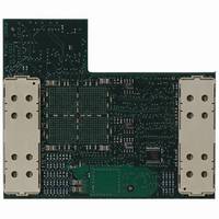
ATICE50POD Atmel, ATICE50POD Datasheet - Page 35

ATICE50POD
Manufacturer Part Number
ATICE50POD
Description
REPLACEMENT POD FOR ICE40,ICE50
Manufacturer
Atmel
Datasheet
1.ATICE50MEM.pdf
(73 pages)
Specifications of ATICE50POD
Accessory Type
POD Replacement Kit
For Use With/related Products
AVR ICE40 and ICE50
Lead Free Status / RoHS Status
Contains lead / RoHS non-compliant
4.1
4.2
4.3
4.3.1
ICE50 User Guide
Connecting
ICE50 for
Emulation
Connecting
ICE50 to host PC
Connecting the
Probe to the
Target Board
Connecting PDIP
Adapters
ICE50 connects to both the PC where the firmware development is being made and the
target application. This section describes the connection procedure.
This section will describe how to connect and configure the ICE50 for correct operation.
This task can be divided in the following tasks:
1. Selecting correct Personality Adapter
2. Connecting the Probe to the Target Board
3. Connecting ICE50 to PC
4. Correct Power-Up Sequence
5. Configuring AVR Studio
Please follow the above description to make sure that the ICE50 is configured properly!
The ICE50 connects to the host PC through a standard COM port. Make sure that the
ICE50 is powered down before connecting the cable between the ICE50 and the host
PC. Use the 9-pin RS-232C cable that is shipped with the ICE50. Connect the male
cable connector to the ICE50 and the female connector to the host PC. The communica-
tion runs at 115200 bit/s, no parity, 8 data bits, 1 stop bit, (N81), and with hardware
handshake.
AVR Studio can not force control over a COM port. If other equipment or software driv-
ers have control of the COM port (eg. IrDA, PDA, Scanner.. ) communication with the
ICE50 will fail. Make sure that no other software has control of the COM port that ICE50
is connected to.
Note:
The Probe is connected to the target board through one of the supplied Personality
Adapters. To ensure correct operation make sure that the correct Personality Adapter is
used.
Before connecting the ICE50 to the target application, make sure that the ICE50 and the
target application are not powered. This also applies when removing the ICE50. When
The USB interface is not supported in the current version of the ICE50. Once
the ICE50 is connected to the host PC, continue with connecting the probe to
the target board.
Connecting ICE50
Section 4
Rev. 2523A–AVR–11/02
4-1


