ATICE50POD Atmel, ATICE50POD Datasheet - Page 37
ATICE50POD
Manufacturer Part Number
ATICE50POD
Description
REPLACEMENT POD FOR ICE40,ICE50
Manufacturer
Atmel
Datasheet
1.ATICE50MEM.pdf
(73 pages)
Specifications of ATICE50POD
Accessory Type
POD Replacement Kit
For Use With/related Products
AVR ICE40 and ICE50
Lead Free Status / RoHS Status
Contains lead / RoHS non-compliant


4.3.2
ICE50 User Guide
Connecting TQFP
Adapters
The m128 TQFP adapter consists of two parts:
1. Start soldering the bottom part of the Personality Adapter on the target applica-
2. Place the TQFP top module on top of the soldered bottom module. Again take
3. Place the Probe on the Personality Adapter.
Use low temperature solder and soldering iron when soldering the bottom part to the tar-
get. This will ensure that the solder on the adapter is not removed during soldering.
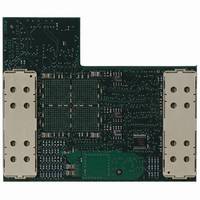
Figure 4-3. Connecting TQFP Adapters (Part One of Three)
Note:
The bottom part that should be soldered into the target application, and the top part
that interface with the ICE50 Probe. When mounting the TQFP adapter, make sure
that the adapter is soldered into the application with the correct orientation.
tion. Make sure that pin 1 on the adapter matches pin 1 in the target application.
care to place it with the correct orientation.
1. Place and solder the bottom module. Take care to place it with correct orientation.
Connecting ICE50
2523A–AVR–11/02
4-3
Related parts for ATICE50POD
Image
Part Number
Description
Manufacturer
Datasheet
Request
R

Part Number:
Description:
EMULATOR IN CIRCUIT MEGAAVR
Manufacturer:
Atmel
Datasheet:

Part Number:
Description:
DEV KIT FOR AVR/AVR32
Manufacturer:
Atmel
Datasheet:

Part Number:
Description:
INTERVAL AND WIPE/WASH WIPER CONTROL IC WITH DELAY
Manufacturer:
ATMEL Corporation
Datasheet:
Part Number:
Description:
Low-Voltage Voice-Switched IC for Hands-Free Operation
Manufacturer:
ATMEL Corporation
Datasheet:
Part Number:
Description:
MONOLITHIC INTEGRATED FEATUREPHONE CIRCUIT
Manufacturer:
ATMEL Corporation
Datasheet:
Part Number:
Description:
AM-FM Receiver IC U4255BM-M
Manufacturer:
ATMEL Corporation
Datasheet:
Part Number:
Description:
Monolithic Integrated Feature Phone Circuit
Manufacturer:
ATMEL Corporation
Datasheet:
Part Number:
Description:
Multistandard Video-IF and Quasi Parallel Sound Processing
Manufacturer:
ATMEL Corporation
Datasheet:
Part Number:
Description:
High-performance EE PLD
Manufacturer:
ATMEL Corporation
Datasheet:
Part Number:
Description:
8-bit Flash Microcontroller
Manufacturer:
ATMEL Corporation
Datasheet:
Part Number:
Description:
2-Wire Serial EEPROM
Manufacturer:
ATMEL Corporation
Datasheet: