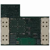
ATICE50POD Atmel, ATICE50POD Datasheet - Page 68

ATICE50POD
Manufacturer Part Number
ATICE50POD
Description
REPLACEMENT POD FOR ICE40,ICE50
Manufacturer
Atmel
Datasheet
1.ATICE50MEM.pdf
(73 pages)
Specifications of ATICE50POD
Accessory Type
POD Replacement Kit
For Use With/related Products
AVR ICE40 and ICE50
Lead Free Status / RoHS Status
Contains lead / RoHS non-compliant
2523A–AVR–11/02
Trace
Table 7-5. MCU Control Instructions
7.4
7.5
7-14
Instruction INSTA
[0..15]
NOP
SLEEP
WDR
BREAK
Accessing
External Data
Memory (ICE50
Trace)
Interrupt
Handling (ICE50
Trace)
PMem Addr [PC
[A0..22]
Address of instruction
Address of instruction
Address of instruction
Address of instruction
Instructions that are accessing data memory have different timing based on whether the
memory is internal or external. For external memory accesses, the timing is again
dependent on the number of wait states. This document does not describe the exact
timings of these instructions, but they are fairly similar to those described above. A full
description of the timing of these instructions can be found in Contents of Trace Window
based on Instruction. It applies to the following instructions: LD (various forms), LDD
(various forms), ST (various forms), STD (various forms), LDS, STS, RCALL, ICALL,
CALL, RET, RETI, PUSH, POP.
Interrupts are asynchronous events to the regular program flow. There is no instruction
associated with the start of the processor handling an interrupt. However, once the pro-
cessor has stored the return address to the stack, it will start to execute code from the
interrupt vector address. An example is shown in below (Figure 7-7 shows the code
being executed), where an interrupt occurs during the execution of the instruction RJMP
-0x0001. The Interrupt Acknowledge (IA) flag is set to “1” as can be seen in Figure 7-8.
When this instruction is completed (two cycle instruction), it can be observed that the
program counter is written to the stack at addresses 0x2F before it starts executing from
the interrupt vector (in this case, interrupt vector 0x000013). After the (in this case very
simple) interrupt program has completed, execution resumes.
Figure 7-7. Example Code
Reg.Val RegFileL
[0..7]
N/A
N/A
N/A
N/A
Dat.Addr
RAM_EEADDR [0..22]
N/A
N/A
N/A
N/A
Dat.Val
N/A
N/A
N/A
N/A
Status Register
N/A
N/A
N/A
N/A
ICE50 User Guide


