130-28029 Parallax Inc, 130-28029 Datasheet - Page 66
130-28029
Manufacturer Part Number
130-28029
Description
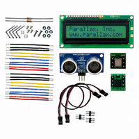
KIT PARTS SMART SENSORS
Manufacturer
Parallax Inc
Datasheet
1.122-28029.pdf
(340 pages)
Specifications of 130-28029
Accessory Type
Education Kit
Product
Microcontroller Accessories
Lead Free Status / RoHS Status
Contains lead / RoHS non-compliant
For Use With/related Products
BASIC Stamp®
Lead Free Status / RoHS Status
Lead free / RoHS Compliant, Contains lead / RoHS non-compliant


Page 54 · Smart Sensors and Applications
All other BASIC Stamp Educational Boards
This section is for connecting the Ping))) sensor and Parallax Serial LCD to one of the
following BASIC Stamp educational boards:
√
√
√
√
√
•
•
•
√
√
Connect the other end of the cable so that the black wire is connected to the
Ping))) module's GND pin, the red wire is connected to the 5 V pin, and the
white wire is connected to the RX pin.
Double-check all your connections, including your jumper setting, and make
sure they are correct.
Plug the power back into the board.
Set the 3-position switch on the Board of Education to 2.
If you have a Board of Education Rev C, Skip to LCD Distance Display on
page 57.
BASIC Stamp HomeWork Board
Board of Education Rev A (Serial version)
Board of Education Rev B (Serial version)
Disconnect power from your board.
Build the breadboard connections as shown in Figure 2-10.
WARNING!
connections are correct.
Parallax Serial LCD could be permanently damaged.
You can also connect the Parallax Serial LCD to Port 14 with a cable. The instructions
are about the same as connecting the Ping))). Start by disconnecting power to your board.
The jumper for Vdd and Vin between the servo ports has to be set to Vdd. The cable has to
be plugged into the X4 header so that the black wire is closest to the X4 label and the white
wire is closest to the 14 label. When connecting the other end of the cable to the Parallax
Serial LCD, make sure the black wire connects to GND, the red wire to 5V, and the white
wire to RX.
Do not connect power to your board until you are positive the
If you make a mistake with the LCD connections, the
Related parts for 130-28029
Image
Part Number
Description
Manufacturer
Datasheet
Request
R

Part Number:
Description:
KIT PROPELLER EDU PROJECT PARTS
Manufacturer:
Parallax Inc
Datasheet:

Part Number:
Description:
KIT PARTS PROCESS CONTROL
Manufacturer:
Parallax Inc
Datasheet:


Part Number:
Description:
Microcontroller Modules & Accessories DISCONTINUED BY PARALLAX
Manufacturer:
Parallax Inc

Part Number:
Description:
BOOK UNDERSTANDING SIGNALS
Manufacturer:
Parallax Inc
Datasheet:


Part Number:
Description:
COMPETITION RING FOR SUMOBOT
Manufacturer:
Parallax Inc
Datasheet:


Part Number:
Description:
TEXT INFRARED REMOTE FOR BOE-BOT
Manufacturer:
Parallax Inc
Datasheet:
Part Number:
Description:
Microcontroller Modules & Accessories DISCONTINUED BY PARALLAX
Manufacturer:
Parallax Inc
Part Number:
Description:
BOOK UNDERSTANDING SIGNALS
Manufacturer:
Parallax Inc
Datasheet:
Part Number:
Description:
BOARD EXPERIMENT+LCD NX-1000
Manufacturer:
Parallax Inc
Datasheet:
Part Number:
Description:
IC MCU 2K FLASH 50MHZ SO-18
Manufacturer:
Parallax Inc
Datasheet: