ATF15XXDK3-SAJ44 Atmel, ATF15XXDK3-SAJ44 Datasheet - Page 18
ATF15XXDK3-SAJ44
Manufacturer Part Number
ATF15XXDK3-SAJ44
Description
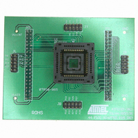
ADAPTER SKT ATF15XXBE 84/44PLCC
Manufacturer
Atmel
Datasheet
1.ATF15XXDK3-SAJ44.pdf
(44 pages)
Specifications of ATF15XXDK3-SAJ44
Module/board Type
Socket Module - PLCC
For Use With/related Products
ATF15xxDK3
Lead Free Status / RoHS Status
Contains lead / RoHS non-compliant


2.1.11
ATF15xx-DK3 Development Kit User Guide
JTAG ISP Connector
and TDO Selection
Jumper
The JTAG ISP Connector, labeled JTAG-IN, is used to connect the ATF15xx’s JTAG
port pins (TCK, TDI, TMS and TDO) through the ISP download cable to the parallel
printer (LPT) port of a PC for JTAG ISP programming of the ATF15xx. Polarized con-
nectors are used on the ATF15xx-DK3 and ISP Download Cable (ATDH1150VPC) Rev
6.0 or later to minimize connection problems. The PIN1 label at the bottom of the JTAG
ISP connector indicates the pin 1 position of the 10-pin header and further reduces the
chance of connecting the ISP Download Cable incorrectly.
To the left of the JTAG-IN connector, there are two columns of vias and they are labeled
JTAG-OUT. They are intended to allow the users to create a JTAG daisy chain to per-
form JTAG operations to multiple devices. Users will need to solder the same type of
connector as the one used for JTAG-IN into the JTAG-OUT position in order to utilize
this available feature.
To create a JTAG daisy chain using multiple ATF15xx-DK3 boards, the TDO Selection
Jumper, labeled JP-TDO, must be set to the appropriate position. For all the devices in
the daisy chain except the last device, this jumper must be set to the “TO NEXT
DEVICE” position. For the last device in the chain, this jumper must be set to the “TO
ISP CABLE” position. When this jumper is in the “TO NEXT DEVICE” position, the TDO
of that particular JTAG device will be connected to the TDI of the next JTAG device in
the chain. When this jumper is in the “TO ISP CABLE” position, the TDO of that device
will be connected to the TDO of the JTAG 10-pin connector, which will allow the TDO
signal of the that device in the chain to be transmitted back to the host PC with the ISP
software. Figure 2-7 below is a circuit diagram of the JTAG connectors and the JP-TDO
jumper. Table 2-15 on page 2-12 lists the pin numbers of the four JTAG pins for the
ATF15xx in all the available packages.
For a single device setup, the position of the JP-TDO jumper must be set to “TO ISP
CABLE”.
Figure 2-7. Circuit Diagram of the JTAG ISP Connectors and TDO Jumper
Hardware Description
3605B–PLD–05/06
2-11
Related parts for ATF15XXDK3-SAJ44
Image
Part Number
Description
Manufacturer
Datasheet
Request
R

Part Number:
Description:
ADAPTER SKT ATF15XXB PLCC/TQFP
Manufacturer:
Atmel
Datasheet:

Part Number:
Description:
ADAPTER SKT ATF15XXBE 84/84PLCC
Manufacturer:
Atmel
Datasheet:

Part Number:
Description:
KIT DEV 20TSSOP ADAPTER ATF15XX
Manufacturer:
Atmel
Datasheet:

Part Number:
Description:
KIT DEV FOR ATF15XX CPLD'S
Manufacturer:
Atmel
Datasheet:
Part Number:
Description:
ADAPTER FOR ATF15XX-DK2 44TQFP
Manufacturer:
Atmel
Datasheet:
Part Number:
Description:
ADAPTER FOR ATF15XX-DK2 44PLCC
Manufacturer:
Atmel
Datasheet:
Part Number:
Description:
ADAPTER FOR ATF15XX-DK2 68PLCC
Manufacturer:
Atmel
Datasheet:
Part Number:
Description:
ADAPTER FOR ATF15XX-DK2 100TQFP
Manufacturer:
Atmel
Datasheet:

Part Number:
Description:
IC TRANS E-PHEMT 2GHZ SOT-343
Manufacturer:
Avago Technologies US Inc.
Datasheet:
Part Number:
Description:
IC TRANS E-PHEMT 2GHZ SOT-343
Manufacturer:
Avago Technologies US Inc.
Datasheet:

Part Number:
Description:
TRANSISTOR,HEMT,N-CHAN,5.5V V(BR)DSS,175mA I(DSS),SOT-343R
Manufacturer:
Avago Technologies US Inc.
Part Number:
Description:
TRANSISTOR,HEMT,N-CHAN,3V V(BR)DSS,15mA I(DSS),SOT-363
Manufacturer:
Avago Technologies US Inc.
Datasheet:
Part Number:
Description:
TRANSISTOR,HEMT,N-CHAN,4.5V V(BR)DSS,90mA I(DSS),SOT-343R
Manufacturer:
Avago Technologies US Inc.
Datasheet: