ATF15XXDK3-SAJ44 Atmel, ATF15XXDK3-SAJ44 Datasheet - Page 20
ATF15XXDK3-SAJ44
Manufacturer Part Number
ATF15XXDK3-SAJ44
Description
ADAPTER SKT ATF15XXBE 84/44PLCC
Manufacturer
Atmel
Datasheet
1.ATF15XXDK3-SAJ44.pdf
(44 pages)
Specifications of ATF15XXDK3-SAJ44
Module/board Type
Socket Module - PLCC
For Use With/related Products
ATF15xxDK3
Lead Free Status / RoHS Status
Contains lead / RoHS non-compliant


2.3
ATF15xx-DK3 Development Kit User Guide
Atmel CPLD ISP
Download Cable
PLCC, and 100-TQFP package types in the ATF15xx family of CPLDs. Socket Adapter
boards for other packages will become available in the near future.
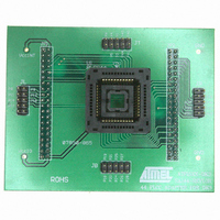
Each socket adapter board contains a socket for the Atmel ATF15xx device and with
male headers on the bottom side, labeled JP1 and JP2. The headers on the bottom side
mate with the female headers on the ATF15xx-DK3 board, labeled JP4 and JP3. The
four 7-segment displays, push-button switches, JTAG port signals, oscillator, VCCINT,
VCCIO, and GND on the CPLD Development/Programmer Board are connected to the
ATF15xx device on the Socket Adapter Board through these two sets of connectors.
On the top of the 44-TQFP socket adapter, there are four 10-pin connectors with the
same dimensions as the JTAG ISP connector. The pins of these four connectors are
connected to the input and I/O pins (except the four JTAG pins) of the target CPLD
device. They can be used to connect to an oscilloscope or logic analyzer to capture the
activities of the input and I/O pins of the CPLD. They also can be used to connect the
input and I/O pins of the CPLD to other external boards or devices for system level eval-
uation or testing.
The Atmel CPLD ISP Download Cable (P/N: ATDH1150VPC) connects the parallel
printer (LPT) port of your PC to the 10-pin JTAG header on the Atmel CPLD Develop-
ment/Programmer Board or a custom circuit board. This is shown in Figure 2-10 on
page 2-14. This ISP cable acts as a buffer to buffer the JTAG signals between the PC’s
LPT port and the ATF15xx on the circuit board. The Power-On LED on the back of the
25-pin male connector housing indicates that the cable is connected properly. Make
sure this LED is turned on before using the Atmel CPLD ISP Software (ATMISP).
This ISP cable consists of a 25-pin (DB25) male connector, which is connected to the
LPT port of a PC. The 10-pin female plug connects to the 10-pin male JTAG header on
the ISP circuit board. The red color stripe on the ribbon cable indicates the orientation of
Pin 1 of the female plug. The 10-pin male JTAG header on the CPLD Development/Pro-
grammer Board is polarized to prevent users from inserting the female plug in the wrong
orientation.
The Atmel CPLD Development/Programmer kits includes an Atmel ISP cable; however,
other supported ISP cables can also be used. The use of the ISP cable on Atmel devel-
opment kit is depending on the device that is selected.
The following shows the appropriate ISP cable that can be used for the different voltage
families of Atmel CPLDs.
1. Atmel-ISP Cable (Rev 4.0 or earlier) can be used for ATF15xxAS/ASL (5.0V)
2. Atmel-ISP Cable (Rev 5.0) can be used for ATF15xxAS/ASL (5.0V) or
3. Atmel-ISP Cable (Rev 6.0), also known as the “Atmel CPLD-ISP MV Cable”,
4. ByteBlaster ISP Cable can be used for ATF15xxAS/ASL (5.0V) device only.
5. ByteBlasterMV ISP Cable can be used for ATF15xxAS/ASL (5.0V) or
6. ByteBlaster II ISP Cable can be used for ATF15xxAS/ASL (5.0V) or
device only.
ATF15xxASV/ASVL (3.3V) device only.
can be used for ATF15xxAS/ASL (5.0V) or ATF15xxASV/ASVL (3.3V) or
ATF15xxBE (1.8V core) device.
ATF15xxASV/ASVL (3.3V) device only.
ATF15xxASV/ASVL (3.3V) or ATF15xxBE (1.8V core) device.
Hardware Description
3605B–PLD–05/06
2-13
Related parts for ATF15XXDK3-SAJ44
Image
Part Number
Description
Manufacturer
Datasheet
Request
R

Part Number:
Description:
ADAPTER SKT ATF15XXB PLCC/TQFP
Manufacturer:
Atmel
Datasheet:

Part Number:
Description:
ADAPTER SKT ATF15XXBE 84/84PLCC
Manufacturer:
Atmel
Datasheet:

Part Number:
Description:
KIT DEV 20TSSOP ADAPTER ATF15XX
Manufacturer:
Atmel
Datasheet:

Part Number:
Description:
KIT DEV FOR ATF15XX CPLD'S
Manufacturer:
Atmel
Datasheet:
Part Number:
Description:
ADAPTER FOR ATF15XX-DK2 44TQFP
Manufacturer:
Atmel
Datasheet:
Part Number:
Description:
ADAPTER FOR ATF15XX-DK2 44PLCC
Manufacturer:
Atmel
Datasheet:
Part Number:
Description:
ADAPTER FOR ATF15XX-DK2 68PLCC
Manufacturer:
Atmel
Datasheet:
Part Number:
Description:
ADAPTER FOR ATF15XX-DK2 100TQFP
Manufacturer:
Atmel
Datasheet:

Part Number:
Description:
IC TRANS E-PHEMT 2GHZ SOT-343
Manufacturer:
Avago Technologies US Inc.
Datasheet:
Part Number:
Description:
IC TRANS E-PHEMT 2GHZ SOT-343
Manufacturer:
Avago Technologies US Inc.
Datasheet:

Part Number:
Description:
TRANSISTOR,HEMT,N-CHAN,5.5V V(BR)DSS,175mA I(DSS),SOT-343R
Manufacturer:
Avago Technologies US Inc.
Part Number:
Description:
TRANSISTOR,HEMT,N-CHAN,3V V(BR)DSS,15mA I(DSS),SOT-363
Manufacturer:
Avago Technologies US Inc.
Datasheet:
Part Number:
Description:
TRANSISTOR,HEMT,N-CHAN,4.5V V(BR)DSS,90mA I(DSS),SOT-343R
Manufacturer:
Avago Technologies US Inc.
Datasheet: