ATF15XXDK3-SAJ44 Atmel, ATF15XXDK3-SAJ44 Datasheet - Page 30
ATF15XXDK3-SAJ44
Manufacturer Part Number
ATF15XXDK3-SAJ44
Description
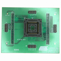
ADAPTER SKT ATF15XXBE 84/44PLCC
Manufacturer
Atmel
Datasheet
1.ATF15XXDK3-SAJ44.pdf
(44 pages)
Specifications of ATF15XXDK3-SAJ44
Module/board Type
Socket Module - PLCC
For Use With/related Products
ATF15xxDK3
Lead Free Status / RoHS Status
Contains lead / RoHS non-compliant


ATF15xx-DK3 Development Kit User Guide
1. You can now proceed to the device fitter portion of the design flow by clicking on
You can either use the default options or specify fitter properties. ProChip Designer will
automatically select the EDIF file (*.EDF) associated to the current design project and
the tool type. In this example, since our target device is an ATF1502BE, we will select
the FIT1502.EXE device fitter.
The fitter creates the important JEDEC and Fit Report output files. They contain the data
for programming the device (using in-system programming or on a third-party device
programmer) and the pin assignments required for board layout respectively.
Please review the Global Device Parameters and Pin/Node Options as well. The help
files also show the Device Pin_Node lists for each of the Atmel CPLDs.
2. Make sure the JTAG box is checked. This enables the JTAG port for ISP
3. Make sure the Pin Fit Control setting is set to Keep. This will ensure that the pin
4. Make sure the Logic Double setting is set to if necessary.
5. When all the fitter options are set, click on the Run Fitter button to fit the design.
(2) Check the
(3) Set the Pin
the Atmel Fitter button.
programming.
assignments in the PLD file will be kept during the place-and-route process.
JTAG box
Fit Control
setting to
Keep
(5) Start the fitting
process
(4) Set Logic Double
to if necessary
CPLD Design Flow Tutorial
(1) Open the Atmel
Fitter window
3605B–PLD–05/06
3-9
Related parts for ATF15XXDK3-SAJ44
Image
Part Number
Description
Manufacturer
Datasheet
Request
R

Part Number:
Description:
ADAPTER SKT ATF15XXB PLCC/TQFP
Manufacturer:
Atmel
Datasheet:

Part Number:
Description:
ADAPTER SKT ATF15XXBE 84/84PLCC
Manufacturer:
Atmel
Datasheet:

Part Number:
Description:
KIT DEV 20TSSOP ADAPTER ATF15XX
Manufacturer:
Atmel
Datasheet:

Part Number:
Description:
KIT DEV FOR ATF15XX CPLD'S
Manufacturer:
Atmel
Datasheet:
Part Number:
Description:
ADAPTER FOR ATF15XX-DK2 44TQFP
Manufacturer:
Atmel
Datasheet:
Part Number:
Description:
ADAPTER FOR ATF15XX-DK2 44PLCC
Manufacturer:
Atmel
Datasheet:
Part Number:
Description:
ADAPTER FOR ATF15XX-DK2 68PLCC
Manufacturer:
Atmel
Datasheet:
Part Number:
Description:
ADAPTER FOR ATF15XX-DK2 100TQFP
Manufacturer:
Atmel
Datasheet:

Part Number:
Description:
IC TRANS E-PHEMT 2GHZ SOT-343
Manufacturer:
Avago Technologies US Inc.
Datasheet:
Part Number:
Description:
IC TRANS E-PHEMT 2GHZ SOT-343
Manufacturer:
Avago Technologies US Inc.
Datasheet:

Part Number:
Description:
TRANSISTOR,HEMT,N-CHAN,5.5V V(BR)DSS,175mA I(DSS),SOT-343R
Manufacturer:
Avago Technologies US Inc.
Part Number:
Description:
TRANSISTOR,HEMT,N-CHAN,3V V(BR)DSS,15mA I(DSS),SOT-363
Manufacturer:
Avago Technologies US Inc.
Datasheet:
Part Number:
Description:
TRANSISTOR,HEMT,N-CHAN,4.5V V(BR)DSS,90mA I(DSS),SOT-343R
Manufacturer:
Avago Technologies US Inc.
Datasheet: