C8051T610DB32 Silicon Laboratories Inc, C8051T610DB32 Datasheet - Page 146
C8051T610DB32
Manufacturer Part Number
C8051T610DB32
Description
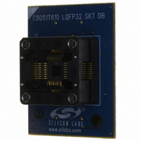
DAUGHT BOARD T610 32TQFP SOCKET
Manufacturer
Silicon Laboratories Inc
Datasheet
1.C8051T610DB32.pdf
(218 pages)
Specifications of C8051T610DB32
Module/board Type
Socket Module - TQFP
Processor To Be Evaluated
C8051T61x
Interface Type
USB
Lead Free Status / RoHS Status
Lead free / RoHS Compliant
For Use With/related Products
C8051T610DK
Lead Free Status / RoHS Status
Lead free / RoHS Compliant, Lead free / RoHS Compliant
Other names
336-1505


C8051T610/1/2/3/4/5/6/7
22.5.4. Read Sequence (Slave)
During a read sequence, an SMBus master reads data from a slave device. The slave in this transfer will
be a receiver during the address byte, and a transmitter during all data bytes. When slave events are
enabled (INH = 0), the interface enters Slave Receiver Mode (to receive the slave address) when a START
followed by a slave address and direction bit (READ in this case) is received. Upon entering Slave
Receiver Mode, an interrupt is generated and the ACKRQ bit is set. The software must respond to the
received slave address with an ACK, or ignore the received slave address with a NACK.
If the received slave address is ignored by software (by NACKing the address), slave interrupts will be
inhibited until the next START is detected. If the received slave address is acknowledged, zero or more
data bytes are transmitted. If the received slave address is acknowledged, data should be written to
SMB0DAT to be transmitted. The interface enters slave transmitter mode, and transmits one or more bytes
of data. After each byte is transmitted, the master sends an acknowledge bit; if the acknowledge bit is an
ACK, SMB0DAT should be written with the next data byte. If the acknowledge bit is a NACK, SMB0DAT
should not be written to before SI is cleared (an error condition may be generated if SMB0DAT is written
following a received NACK while in slave transmitter mode). The interface exits slave transmitter mode
after receiving a STOP. Note that the interface will switch to slave receiver mode if SMB0DAT is not written
following a Slave Transmitter interrupt. Figure 22.8 shows a typical slave read sequence. Two transmitted
data bytes are shown, though any number of bytes may be transmitted. Notice that all of the “data byte
transferred” interrupts occur after the ACK cycle in this mode.
22.6. SMBus Status Decoding
The current SMBus status can be easily decoded using the SMB0CN register. Table 22.4 describes the
typical actions taken by firmware on each condition. In the table, STATUS VECTOR refers to the four upper
bits of SMB0CN: MASTER, TXMODE, STA, and STO. The shown response options are only the typical
responses; application-specific procedures are allowed as long as they conform to the SMBus specifica-
tion. Highlighted responses are allowed by hardware but do not conform to the SMBus specification.
146
S
Received by SMBus
Interface
Transmitted by
SMBus Interface
SLA
Figure 22.8. Typical Slave Read Sequence
R
A
Data Byte
Rev 1.0
Interrupt Locations
A
S = START
P = STOP
N = NACK
R = READ
SLA = Slave Address
Data Byte
N
P
Related parts for C8051T610DB32
Image
Part Number
Description
Manufacturer
Datasheet
Request
R

Part Number:
Description:
SMD/C°/SINGLE-ENDED OUTPUT SILICON OSCILLATOR
Manufacturer:
Silicon Laboratories Inc
Part Number:
Description:
Manufacturer:
Silicon Laboratories Inc
Datasheet:
Part Number:
Description:
N/A N/A/SI4010 AES KEYFOB DEMO WITH LCD RX
Manufacturer:
Silicon Laboratories Inc
Datasheet:
Part Number:
Description:
N/A N/A/SI4010 SIMPLIFIED KEY FOB DEMO WITH LED RX
Manufacturer:
Silicon Laboratories Inc
Datasheet:
Part Number:
Description:
N/A/-40 TO 85 OC/EZLINK MODULE; F930/4432 HIGH BAND (REV E/B1)
Manufacturer:
Silicon Laboratories Inc
Part Number:
Description:
EZLink Module; F930/4432 Low Band (rev e/B1)
Manufacturer:
Silicon Laboratories Inc
Part Number:
Description:
I°/4460 10 DBM RADIO TEST CARD 434 MHZ
Manufacturer:
Silicon Laboratories Inc
Part Number:
Description:
I°/4461 14 DBM RADIO TEST CARD 868 MHZ
Manufacturer:
Silicon Laboratories Inc
Part Number:
Description:
I°/4463 20 DBM RFSWITCH RADIO TEST CARD 460 MHZ
Manufacturer:
Silicon Laboratories Inc
Part Number:
Description:
I°/4463 20 DBM RADIO TEST CARD 868 MHZ
Manufacturer:
Silicon Laboratories Inc
Part Number:
Description:
I°/4463 27 DBM RADIO TEST CARD 868 MHZ
Manufacturer:
Silicon Laboratories Inc
Part Number:
Description:
I°/4463 SKYWORKS 30 DBM RADIO TEST CARD 915 MHZ
Manufacturer:
Silicon Laboratories Inc
Part Number:
Description:
N/A N/A/-40 TO 85 OC/4463 RFMD 30 DBM RADIO TEST CARD 915 MHZ
Manufacturer:
Silicon Laboratories Inc
Part Number:
Description:
I°/4463 20 DBM RADIO TEST CARD 169 MHZ
Manufacturer:
Silicon Laboratories Inc