C8051T600SDB Silicon Laboratories Inc, C8051T600SDB Datasheet - Page 41
C8051T600SDB
Manufacturer Part Number
C8051T600SDB
Description
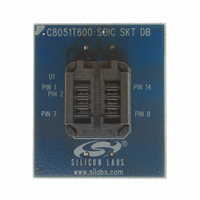
BOARD SOCKET DAUGHTER SOIC
Manufacturer
Silicon Laboratories Inc
Datasheet
1.C8051T600EDB.pdf
(188 pages)
Specifications of C8051T600SDB
Module/board Type
Socket Module - SOIC
Data Bus Width
8 bit
Operating Supply Voltage
+ 1.8 V to + 3.6 V
Lead Free Status / RoHS Status
Contains lead / RoHS non-compliant
For Use With/related Products
C8051T600DK
Lead Free Status / Rohs Status
Lead free / RoHS Compliant
Other names
336-1405


9.1. Output Code Formatting
The ADC measures the input voltage with reference to GND. The registers ADC0H and ADC0L contain the
high and low bytes of the output conversion code from the ADC at the completion of each conversion. Data
can be right-justified or left-justified, depending on the setting of the AD0LJST bit. Conversion codes are
represented as 10-bit unsigned integers. Inputs are measured from 0 to VREF x 1023/1024. Example
codes are shown below for both right-justified and left-justified data. Unused bits in the ADC0H and ADC0L
registers are set to 0.
9.2. 8-Bit Mode
Setting the ADC08BE bit in register ADC0CF to 1 will put the ADC in 8-bit mode. In 8-bit mode, only the 8
MSBs of data are converted, and the ADC0H register holds the results. The AD0LJST bit is ignored for 8-
bit mode. 8-bit conversions take two fewer SAR clock cycles than 10-bit conversions, so the conversion is
completed faster, and a 500 ksps sampling rate can be achieved with a slower SAR clock.
9.3. Modes of Operation
ADC0 has a maximum conversion speed of 500 ksps. The ADC0 conversion clock is a divided version of
the system clock, determined by the AD0SC bits in the ADC0CF register.
9.3.1. Starting a Conversion
A conversion can be initiated in one of six ways, depending on the programmed states of the ADC0 Start of
Conversion Mode bits (AD0CM2–0) in register ADC0CN. Conversions may be initiated by one of the fol-
lowing:
1. Writing a 1 to the AD0BUSY bit of register ADC0CN
2. A Timer 0 overflow (i.e., timed continuous conversions)
3. A Timer 2 overflow
4. A Timer 1 overflow
5. A rising edge on the CNVSTR input signal
6. A Timer 3 overflow
Writing a 1 to AD0BUSY provides software control of ADC0 whereby conversions are performed "on-
demand". During conversion, the AD0BUSY bit is set to logic 1 and reset to logic 0 when the conversion is
complete. The falling edge of AD0BUSY triggers an interrupt (when enabled) and sets the ADC0 interrupt
flag (AD0INT). Note: When polling for ADC conversion completions, the ADC0 interrupt flag (AD0INT)
should be used. Converted data is available in the ADC0 data registers, ADC0H:ADC0L, when bit AD0INT
is logic 1. Note that when Timer 2 or Timer 3 overflows are used as the conversion source, Low Byte over-
flows are used if Timer 2/3 is in 8-bit mode. High byte overflows are used if Timer 2/3 is in 16-bit mode.
See Section “25. Timers” on page 145 for timer configuration.
Important Note About Using CNVSTR: The CNVSTR input pin also functions as a Port I/O pin. When the
CNVSTR input is used as the ADC0 conversion source, the associated pin should be skipped by the Digi-
tal Crossbar. See Section “22. Port Input/Output” on page 106 for details on Port I/O configuration.
Input Voltage
VREF x 1023/1024
VREF x 512/1024
VREF x 256/1024
0
Right-Justified ADC0H:ADC0L
(AD0LJST = 0)
0x03FF
0x0200
0x0100
0x0000
Rev. 1.2
C8051T600/1/2/3/4/5/6
Left-Justified ADC0H:ADC0L
(AD0LJST = 1)
0xFFC0
0x8000
0x4000
0x0000
41
Related parts for C8051T600SDB
Image
Part Number
Description
Manufacturer
Datasheet
Request
R

Part Number:
Description:
SMD/C°/SINGLE-ENDED OUTPUT SILICON OSCILLATOR
Manufacturer:
Silicon Laboratories Inc
Part Number:
Description:
Manufacturer:
Silicon Laboratories Inc
Datasheet:
Part Number:
Description:
N/A N/A/SI4010 AES KEYFOB DEMO WITH LCD RX
Manufacturer:
Silicon Laboratories Inc
Datasheet:
Part Number:
Description:
N/A N/A/SI4010 SIMPLIFIED KEY FOB DEMO WITH LED RX
Manufacturer:
Silicon Laboratories Inc
Datasheet:
Part Number:
Description:
N/A/-40 TO 85 OC/EZLINK MODULE; F930/4432 HIGH BAND (REV E/B1)
Manufacturer:
Silicon Laboratories Inc
Part Number:
Description:
EZLink Module; F930/4432 Low Band (rev e/B1)
Manufacturer:
Silicon Laboratories Inc
Part Number:
Description:
I°/4460 10 DBM RADIO TEST CARD 434 MHZ
Manufacturer:
Silicon Laboratories Inc
Part Number:
Description:
I°/4461 14 DBM RADIO TEST CARD 868 MHZ
Manufacturer:
Silicon Laboratories Inc
Part Number:
Description:
I°/4463 20 DBM RFSWITCH RADIO TEST CARD 460 MHZ
Manufacturer:
Silicon Laboratories Inc
Part Number:
Description:
I°/4463 20 DBM RADIO TEST CARD 868 MHZ
Manufacturer:
Silicon Laboratories Inc
Part Number:
Description:
I°/4463 27 DBM RADIO TEST CARD 868 MHZ
Manufacturer:
Silicon Laboratories Inc
Part Number:
Description:
I°/4463 SKYWORKS 30 DBM RADIO TEST CARD 915 MHZ
Manufacturer:
Silicon Laboratories Inc
Part Number:
Description:
N/A N/A/-40 TO 85 OC/4463 RFMD 30 DBM RADIO TEST CARD 915 MHZ
Manufacturer:
Silicon Laboratories Inc
Part Number:
Description:
I°/4463 20 DBM RADIO TEST CARD 169 MHZ
Manufacturer:
Silicon Laboratories Inc