C8051T600QDB Silicon Laboratories Inc, C8051T600QDB Datasheet - Page 123
C8051T600QDB
Manufacturer Part Number
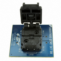
C8051T600QDB
Description
BOARD SOCKET DAUGHTER QFN
Manufacturer
Silicon Laboratories Inc
Datasheet
1.C8051T600EDB.pdf
(188 pages)
Specifications of C8051T600QDB
Module/board Type
Socket Module - QFN
Data Bus Width
8 bit
Operating Supply Voltage
+ 1.8 V to + 3.6 V
Lead Free Status / RoHS Status
Contains lead / RoHS non-compliant
For Use With/related Products
C8051T600DK
Lead Free Status / Rohs Status
Lead free / RoHS Compliant
Other names
336-1406


When the SMBTOE bit in SMB0CF is set, Timer 3 is used to detect SCL low timeouts. Timer 3 is forced to
reload when SCL is high, and allowed to count when SCL is low. With Timer 3 enabled and configured to
overflow after 25 ms (and SMBTOE set), the Timer 3 interrupt service routine can be used to reset (disable
and re-enable) the SMBus in the event of an SCL low timeout.
23.3.5. SCL High (SMBus Free) Timeout
The SMBus specification stipulates that if the SCL and SDA lines remain high for more than 50 µs, the bus
is designated as free. When the SMBFTE bit in SMB0CF is set, the bus will be considered free if SCL and
SDA remain high for more than 10 SMBus clock source periods (as defined by the timer configured for the
SMBus clock source). If the SMBus is waiting to generate a Master START, the START will be generated
following this timeout. A clock source is required for free timeout detection, even in a slave-only implemen-
tation.
23.4. Using the SMBus
The SMBus can operate in both Master and Slave modes. The interface provides timing and shifting con-
trol for serial transfers; higher level protocol is determined by user software. The SMBus interface provides
the following application-independent features:
SMBus interrupts are generated for each data byte or slave address that is transferred. When a transmitter
(i.e., sending address/data, receiving an ACK), this interrupt is generated after the ACK cycle so that soft-
ware may read the received ACK value; when receiving data (i.e., receiving address/data, sending an
ACK), this interrupt is generated before the ACK cycle so that software may define the outgoing ACK
value. See Section 23.5 for more details on transmission sequences.
Interrupts are also generated to indicate the beginning of a transfer when a master (START generated) or
the end of a transfer when a slave (STOP detected). Software should read the SMB0CN (SMBus Control
register) to find the cause of the SMBus interrupt. The SMB0CN register is described in Section 23.4.2;
Table 23.4 provides a quick SMB0CN decoding reference.
23.4.1. SMBus Configuration Register
The SMBus Configuration register (SMB0CF) is used to enable the SMBus Master and/or Slave modes,
select the SMBus clock source, and select the SMBus timing and timeout options. When the ENSMB bit is
set, the SMBus is enabled for all master and slave events. Slave events may be disabled by setting the
INH bit. With slave events inhibited, the SMBus interface will still monitor the SCL and SDA pins; however,
the interface will NACK all received addresses and will not generate any slave interrupts. When the INH bit
is set, all slave events will be inhibited following the next START (interrupts will continue for the duration of
the current transfer).
Byte-wise serial data transfers
Clock signal generation on SCL (Master Mode only) and SDA data synchronization
Timeout/bus error recognition, as defined by the SMB0CF configuration register
START/STOP timing, detection, and generation
Bus arbitration
Interrupt generation
Status information
Rev. 1.2
C8051T600/1/2/3/4/5/6
123
Related parts for C8051T600QDB
Image
Part Number
Description
Manufacturer
Datasheet
Request
R

Part Number:
Description:
SMD/C°/SINGLE-ENDED OUTPUT SILICON OSCILLATOR
Manufacturer:
Silicon Laboratories Inc
Part Number:
Description:
Manufacturer:
Silicon Laboratories Inc
Datasheet:
Part Number:
Description:
N/A N/A/SI4010 AES KEYFOB DEMO WITH LCD RX
Manufacturer:
Silicon Laboratories Inc
Datasheet:
Part Number:
Description:
N/A N/A/SI4010 SIMPLIFIED KEY FOB DEMO WITH LED RX
Manufacturer:
Silicon Laboratories Inc
Datasheet:
Part Number:
Description:
N/A/-40 TO 85 OC/EZLINK MODULE; F930/4432 HIGH BAND (REV E/B1)
Manufacturer:
Silicon Laboratories Inc
Part Number:
Description:
EZLink Module; F930/4432 Low Band (rev e/B1)
Manufacturer:
Silicon Laboratories Inc
Part Number:
Description:
I°/4460 10 DBM RADIO TEST CARD 434 MHZ
Manufacturer:
Silicon Laboratories Inc
Part Number:
Description:
I°/4461 14 DBM RADIO TEST CARD 868 MHZ
Manufacturer:
Silicon Laboratories Inc
Part Number:
Description:
I°/4463 20 DBM RFSWITCH RADIO TEST CARD 460 MHZ
Manufacturer:
Silicon Laboratories Inc
Part Number:
Description:
I°/4463 20 DBM RADIO TEST CARD 868 MHZ
Manufacturer:
Silicon Laboratories Inc
Part Number:
Description:
I°/4463 27 DBM RADIO TEST CARD 868 MHZ
Manufacturer:
Silicon Laboratories Inc
Part Number:
Description:
I°/4463 SKYWORKS 30 DBM RADIO TEST CARD 915 MHZ
Manufacturer:
Silicon Laboratories Inc
Part Number:
Description:
N/A N/A/-40 TO 85 OC/4463 RFMD 30 DBM RADIO TEST CARD 915 MHZ
Manufacturer:
Silicon Laboratories Inc
Part Number:
Description:
I°/4463 20 DBM RADIO TEST CARD 169 MHZ
Manufacturer:
Silicon Laboratories Inc