C8051T600QDB Silicon Laboratories Inc, C8051T600QDB Datasheet - Page 2
C8051T600QDB
Manufacturer Part Number
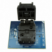
C8051T600QDB
Description
BOARD SOCKET DAUGHTER QFN
Manufacturer
Silicon Laboratories Inc
Datasheet
1.C8051T600EDB.pdf
(188 pages)
Specifications of C8051T600QDB
Module/board Type
Socket Module - QFN
Data Bus Width
8 bit
Operating Supply Voltage
+ 1.8 V to + 3.6 V
Lead Free Status / RoHS Status
Contains lead / RoHS non-compliant
For Use With/related Products
C8051T600DK
Lead Free Status / Rohs Status
Lead free / RoHS Compliant
Other names
336-1406


C8051T600/1/2/3/4/5/6
Table of Contents
1. System Overview ..................................................................................................... 13
2. Ordering Information ............................................................................................... 16
3. Pin Definitions.......................................................................................................... 17
4. QFN-11 Package Specifications ............................................................................. 22
5. SOIC-14 Package Specifications ............................................................................ 24
6. MSOP-10 Package Specifications .......................................................................... 26
7. QFN-10 Package Specifications ............................................................................. 28
8. Electrical Characteristics ........................................................................................ 30
9. 10-Bit ADC (ADC0, C8051T600/2/4 only)................................................................ 40
10. Temperature Sensor (C8051T600/2/4 only) ......................................................... 52
11. Voltage Reference Options ................................................................................... 55
12. Voltage Regulator (REG0) ..................................................................................... 57
13. Comparator0........................................................................................................... 59
14. CIP-51 Microcontroller........................................................................................... 65
15. Memory Organization ............................................................................................ 74
16. Special Function Registers................................................................................... 77
17. Interrupts ................................................................................................................ 80
2
8.1. Absolute Maximum Specifications..................................................................... 30
8.2. Electrical Characteristics ................................................................................... 31
8.3. Typical Performance Curves ............................................................................. 38
9.1. Output Code Formatting .................................................................................... 41
9.2. 8-Bit Mode ......................................................................................................... 41
9.3. Modes of Operation ........................................................................................... 41
9.4. Programmable Window Detector....................................................................... 47
9.5. ADC0 Analog Multiplexer (C8051T600/2/4 only)............................................... 50
10.1. Calibration ....................................................................................................... 52
13.1. Comparator Multiplexer ................................................................................... 63
14.1. Instruction Set.................................................................................................. 66
14.2. CIP-51 Register Descriptions .......................................................................... 71
15.1. Program Memory............................................................................................. 74
15.2. Data Memory ................................................................................................... 75
17.1. MCU Interrupt Sources and Vectors................................................................ 81
9.3.1. Starting a Conversion................................................................................ 41
9.3.2. Tracking Modes......................................................................................... 42
9.3.3. Settling Time Requirements...................................................................... 43
9.4.1. Window Detector Example........................................................................ 49
14.1.1. Instruction and CPU Timing .................................................................... 66
15.2.1. Internal RAM ........................................................................................... 75
17.1.1. Interrupt Priorities.................................................................................... 81
17.1.2. Interrupt Latency ..................................................................................... 81
15.2.1.1. General Purpose Registers ............................................................ 76
15.2.1.2. Bit Addressable Locations .............................................................. 76
15.2.1.3. Stack ............................................................................................ 76
Rev. 1.2
Related parts for C8051T600QDB
Image
Part Number
Description
Manufacturer
Datasheet
Request
R

Part Number:
Description:
SMD/C°/SINGLE-ENDED OUTPUT SILICON OSCILLATOR
Manufacturer:
Silicon Laboratories Inc
Part Number:
Description:
Manufacturer:
Silicon Laboratories Inc
Datasheet:
Part Number:
Description:
N/A N/A/SI4010 AES KEYFOB DEMO WITH LCD RX
Manufacturer:
Silicon Laboratories Inc
Datasheet:
Part Number:
Description:
N/A N/A/SI4010 SIMPLIFIED KEY FOB DEMO WITH LED RX
Manufacturer:
Silicon Laboratories Inc
Datasheet:
Part Number:
Description:
N/A/-40 TO 85 OC/EZLINK MODULE; F930/4432 HIGH BAND (REV E/B1)
Manufacturer:
Silicon Laboratories Inc
Part Number:
Description:
EZLink Module; F930/4432 Low Band (rev e/B1)
Manufacturer:
Silicon Laboratories Inc
Part Number:
Description:
I°/4460 10 DBM RADIO TEST CARD 434 MHZ
Manufacturer:
Silicon Laboratories Inc
Part Number:
Description:
I°/4461 14 DBM RADIO TEST CARD 868 MHZ
Manufacturer:
Silicon Laboratories Inc
Part Number:
Description:
I°/4463 20 DBM RFSWITCH RADIO TEST CARD 460 MHZ
Manufacturer:
Silicon Laboratories Inc
Part Number:
Description:
I°/4463 20 DBM RADIO TEST CARD 868 MHZ
Manufacturer:
Silicon Laboratories Inc
Part Number:
Description:
I°/4463 27 DBM RADIO TEST CARD 868 MHZ
Manufacturer:
Silicon Laboratories Inc
Part Number:
Description:
I°/4463 SKYWORKS 30 DBM RADIO TEST CARD 915 MHZ
Manufacturer:
Silicon Laboratories Inc
Part Number:
Description:
N/A N/A/-40 TO 85 OC/4463 RFMD 30 DBM RADIO TEST CARD 915 MHZ
Manufacturer:
Silicon Laboratories Inc
Part Number:
Description:
I°/4463 20 DBM RADIO TEST CARD 169 MHZ
Manufacturer:
Silicon Laboratories Inc