C8051T610DB28 Silicon Laboratories Inc, C8051T610DB28 Datasheet - Page 203
C8051T610DB28
Manufacturer Part Number
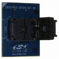
C8051T610DB28
Description
DAUGHTER BOARD T610 28QFN SOCKET
Manufacturer
Silicon Laboratories Inc
Datasheet
1.C8051T610DB32.pdf
(218 pages)
Specifications of C8051T610DB28
Module/board Type
Socket Module - QFN
Processor To Be Evaluated
C8051T61x
Interface Type
USB
Lead Free Status / RoHS Status
Lead free / RoHS Compliant
For Use With/related Products
C8051T610DK
Lead Free Status / RoHS Status
Lead free / RoHS Compliant, Lead free / RoHS Compliant
Other names
336-1506


26.5. Register Descriptions for PCA0
Following are detailed descriptions of the special function registers related to the operation of the PCA.
SFR Definition 26.1. PCA0CN: PCA Control
SFR Address = 0xD8; Bit-Addressable
Name
Reset
Bit
Type
7
6
5
2
1
2
1
0
Bit
Unused
Name
CCF4
CCF3
CCF2
CCF1
CCF0
CR
CF
R/W
CF
7
0
PCA Counter/Timer Overflow Flag.
Set by hardware when the PCA Counter/Timer overflows from 0xFFFF to 0x0000.
When the Counter/Timer Overflow (CF) interrupt is enabled, setting this bit causes the
CPU to vector to the PCA interrupt service routine. This bit is not automatically cleared
by hardware and must be cleared by software.
PCA Counter/Timer Run Control.
This bit enables/disables the PCA Counter/Timer.
0: PCA Counter/Timer disabled.
1: PCA Counter/Timer enabled.
Unused. Read = 0b, Write = Don't care.
PCA Module 4 Capture/Compare Flag.
This bit is set by hardware when a match or capture occurs. When the CCF4 interrupt
is enabled, setting this bit causes the CPU to vector to the PCA interrupt service rou-
tine. This bit is not automatically cleared by hardware and must be cleared by software.
PCA Module 3 Capture/Compare Flag.
This bit is set by hardware when a match or capture occurs. When the CCF3 interrupt
is enabled, setting this bit causes the CPU to vector to the PCA interrupt service rou-
tine. This bit is not automatically cleared by hardware and must be cleared by software.
PCA Module 2 Capture/Compare Flag.
This bit is set by hardware when a match or capture occurs. When the CCF2 interrupt
is enabled, setting this bit causes the CPU to vector to the PCA interrupt service rou-
tine. This bit is not automatically cleared by hardware and must be cleared by software.
PCA Module 1 Capture/Compare Flag.
This bit is set by hardware when a match or capture occurs. When the CCF1 interrupt
is enabled, setting this bit causes the CPU to vector to the PCA interrupt service rou-
tine. This bit is not automatically cleared by hardware and must be cleared by software.
PCA Module 0 Capture/Compare Flag.
This bit is set by hardware when a match or capture occurs. When the CCF0 interrupt
is enabled, setting this bit causes the CPU to vector to the PCA interrupt service rou-
tine. This bit is not automatically cleared by hardware and must be cleared by software.
R/W
CR
6
0
R
5
0
CCF4
R/W
Rev 1.0
4
0
C8051T610/1/2/3/4/5/6/7
Function
CCF3
R/W
3
0
CCF2
R/W
2
0
CCF1
R/W
1
0
CCF0
R/W
0
0
203
Related parts for C8051T610DB28
Image
Part Number
Description
Manufacturer
Datasheet
Request
R

Part Number:
Description:
SMD/C°/SINGLE-ENDED OUTPUT SILICON OSCILLATOR
Manufacturer:
Silicon Laboratories Inc
Part Number:
Description:
Manufacturer:
Silicon Laboratories Inc
Datasheet:
Part Number:
Description:
N/A N/A/SI4010 AES KEYFOB DEMO WITH LCD RX
Manufacturer:
Silicon Laboratories Inc
Datasheet:
Part Number:
Description:
N/A N/A/SI4010 SIMPLIFIED KEY FOB DEMO WITH LED RX
Manufacturer:
Silicon Laboratories Inc
Datasheet:
Part Number:
Description:
N/A/-40 TO 85 OC/EZLINK MODULE; F930/4432 HIGH BAND (REV E/B1)
Manufacturer:
Silicon Laboratories Inc
Part Number:
Description:
EZLink Module; F930/4432 Low Band (rev e/B1)
Manufacturer:
Silicon Laboratories Inc
Part Number:
Description:
I°/4460 10 DBM RADIO TEST CARD 434 MHZ
Manufacturer:
Silicon Laboratories Inc
Part Number:
Description:
I°/4461 14 DBM RADIO TEST CARD 868 MHZ
Manufacturer:
Silicon Laboratories Inc
Part Number:
Description:
I°/4463 20 DBM RFSWITCH RADIO TEST CARD 460 MHZ
Manufacturer:
Silicon Laboratories Inc
Part Number:
Description:
I°/4463 20 DBM RADIO TEST CARD 868 MHZ
Manufacturer:
Silicon Laboratories Inc
Part Number:
Description:
I°/4463 27 DBM RADIO TEST CARD 868 MHZ
Manufacturer:
Silicon Laboratories Inc
Part Number:
Description:
I°/4463 SKYWORKS 30 DBM RADIO TEST CARD 915 MHZ
Manufacturer:
Silicon Laboratories Inc
Part Number:
Description:
N/A N/A/-40 TO 85 OC/4463 RFMD 30 DBM RADIO TEST CARD 915 MHZ
Manufacturer:
Silicon Laboratories Inc
Part Number:
Description:
I°/4463 20 DBM RADIO TEST CARD 169 MHZ
Manufacturer:
Silicon Laboratories Inc