OM6290 NXP Semiconductors, OM6290 Datasheet
OM6290
Specifications of OM6290


Related parts for OM6290


OM6290 Summary of contents
Page 1
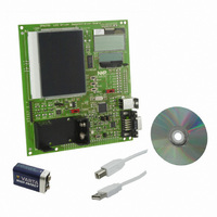
... LCD driver, segment driver, character driver, graphic driver, PCF8576D, PCF2119, PCF8531, PCA9633, ARM7, LPC2148, battery powered, USB Abstract The OM6290 is a LCD driver evaluation board which can be used to demonstrate and evaluate three different types of LCD drivers: The PCF8576D is a segment driver, the PCF2119 a character driver and the PCF8531 a dot matrix driver ...
Page 2
... Date Description 01 20080808 Initial version Contact information For additional information, please visit: For sales office addresses, please send an email to: UM10300_1 User manual http://www.nxp.com salesaddresses@nxp.com Rev 1.0 — 8 August 2008 UM10300 User Manual OM6290 © NXP B.V. 2008. All rights reserved ...
Page 3
... NXP Semiconductors 1. Introduction This User Manual describes the OM6290 LCD Demo board. This board was developed in order to provide a tool for application engineers and development engineers wishing to try and evaluate the possibilities of some of our LCD driver IC’s and to get hands-on experience with writing code for these drivers. Code written using this board can be used in the final application which enables rapid prototyping ...
Page 4
... PCA9633 LED driver. On the top right LCD2 is present and the smaller display below LCD2 is LCD1. Fig 1. Top view of LCD Demoboard UM10300_1 User manual Rev. 1.0— 8 August 2008 UM10300 User Manual OM6290 © NXP B.V. 2008. All rights reserved ...
Page 5
... Switch S1 can be used to select “Program Internal Flash” of the LPC2148 in order to program modified firmware let the LPC2148 boot from its internal flash. The OM6290 is a USB-powered device. Alternatively the board can be powered using a standard 9V (6LR61 / PP3) battery. A battery holder is present on the board and switch S2, located between the battery holder and LCD3, can be used to select either USB- power or battery power ...
Page 6
... Pot1 (4k7) instead. This enables adjustment of the contrast of display LCD3. The location of these components is between LCD2 and LCD3. UM10300_1 User manual . A common value for the required load L Rev. 1.0— 8 August 2008 UM10300 User Manual OM6290 © NXP B.V. 2008. All rights reserved ...
Page 7
... NXP Semiconductors 2.6 Hardware requirements In order to be able to modify the firmware of the OM6290 Demo Board you need: • The OM6290 Demo Board • An IBM-compatible PC with an unused USB port to supply power to the board (alternatively via a battery) and an unused RS232 COM port for Flash In-System Programming (ISP) via the Serial Interface. • ...
Page 8
... High segment count, leading in number of segments supported per single device 160 x 4; • AEC-Q100 automotive qualification. • Separate icon row for versatile usage. Rev. 1.0— 8 August 2008 UM10300 User Manual OM6290 © NXP B.V. 2008. All rights reserved ...
Page 9
... Resolutions that are not common in the market 128 133 128. • twenty 8-segment numeric characters • ten 15-segment alphanumeric characters • any graphics 160 elements 2 C-bus interface Rev. 1.0— 8 August 2008 UM10300 User Manual OM6290 © NXP B.V. 2008. All rights reserved ...
Page 10
... COMMAND POWER-ON OSCILLATOR DECODER RESET 2 INPUT I C-BUS FILTERS CONTROLLER 53 SA0 Rev. 1.0— 8 August 2008 UM10300 User Manual OM6290 S0 to S39 BP2 BP1 BP3 DISPLAY SEGMENT OUTPUTS OUTPUTS DISPLAY REGISTER OUTPUT BANK SELECT DISPLAY AND BLINK CONTROL DISPLAY RAM 40 × 4-BIT ...
Page 11
... V DD2 value and LCD liquid properties) DD2 • Icon mode: <25 μA • Power-down mode: <2 μA. Rev. 1.0— 8 August 2008 UM10300 User Manual OM6290 , programmable by instruction 1.5 to 5.5 V (chip may be driven with = 2 − 2 and DD3 SS © ...
Page 12
... FLAG REGISTER 8 I/O BUFFER 160 to 162 164 to 167 19 158 DB4 to DB7 E RS DB0 to DB2 R/W Rev. 1.0— 8 August 2008 UM10300 User Manual OM6290 R17DUP R1 to R18 100 51 to 59, 141 to 149 18 ROW DRIVERS 18 SHIFT REGISTER 18-BIT OSCILLATOR CHARACTER GENERATOR ROM (CGROM) ...
Page 13
... Power-on reset DD1 SS1 is 2 LCD • Normal mode • Icon mode Rev. 1.0— 8 August 2008 UM10300 User Manual OM6290 ) can be used and the switching is 1.8 to 5.5 V and DD2 DD3 SS1 SS © NXP B.V. 2008. All rights reserved ...
Page 14
... LATCHES GENERATOR DISPLAY DATA RAM V LCD MATRIX DATA GENERATOR RAM SCL 2 INPUT I C-BUS FILTERS CONTROL SA0 Rev. 1.0— 8 August 2008 UM10300 User Manual OM6290 DD1 DD2 DD3 128 POWER-ON RESET ENR INTERNAL RES RESET OSC OSCILLATOR TIMING GENERATOR DISPLAY ADDRESS ...
Page 15
... The debugger supports programs that are 16K Bytes or smaller; UM10300_1 User manual 2 C, two UARTs, one SPI, and one SSP (registration required). The RealView MDK Rev. 1.0— 8 August 2008 UM10300 User Manual OM6290 © NXP B.V. 2008. All rights reserved ...
Page 16
... In Fig 5 a screenshot of the KEIL IDE is shown while the current firmware was being modified. For a full overview of available support tools (IDE) visit the NXP website. Fig 5. Screen shot of Keil μVision3 and firmware UM10300_1 User manual Rev. 1.0— 8 August 2008 UM10300 User Manual OM6290 © NXP B.V. 2008. All rights reserved ...
Page 17
... To download the code to the board, follow the instruction for Flash Magic in section 5.2. To create a new project to run on the LCD Eval Board, select The IDE has to be configured for the microcontroller used on the OM6290 board. In order to do so, select “Project” -> “New μVision Project” and enter a project name, after which a window similar to that indicated in Fig 6 pops up ...
Page 18
... As the crystal used on the board is a 12MHz crystal, the setting in the IDE has to correspond with that. In order to achieve this, select Project -> Options for Target ‘OM6290’. The window below pops up. Set the Xtal frequency to 12 MHz. The ARM7 CPU is capable of executing two instruction sets; the ARM instruction set which is 32 bits wide or the Thumb instruction set which is 16 bits wide ...
Page 19
... R/W: Read and Write. This is data. Fig 8. Linker options 5.1.3 Selection of the toolset The downloaded demoboard firmware contains the file ‘OM6290 Demoboard.Uv2’ which is the project configuration file. All settings are correct. In case settings are made manually the information provided here is useful. ...
Page 20
... Ability to automatically program checksums. Using the supplied checksum calculation routine the firmware can easily verify the integrity of a Flash block, ensuring no unauthorized or corrupted code can ever be executed; UM10300_1 User manual Rev. 1.0— 8 August 2008 UM10300 User Manual OM6290 © NXP B.V. 2008. All rights reserved ...
Page 21
... Displays information about the selected Hex File, including the creation and modification dates, flash memory used, percentage of the current device used • For more information visit www.flashmagictool.com UM10300_1 User manual Rev. 1.0— 8 August 2008 UM10300 User Manual OM6290 © NXP B.V. 2008. All rights reserved ...
Page 22
... Flash+Code Rd Prot’ may help. RealView generates smaller files and checking this option will clear all flash. For subsequent modifications, this option can then be unchecked again. UM10300_1 User manual Rev. 1.0— 8 August 2008 UM10300 User Manual OM6290 © NXP B.V. 2008. All rights reserved ...
Page 23
... NXP Semiconductors 6. Flash Magic Quick Start Setting up the OM6290 board is easy and explanations for the board setup are given here. In stand-alone mode only a 9V battery is used to provide power to the board and let the onboard program run. The board is protected against reversed polarisation of the supply voltage ...
Page 24
... To facilitate the understanding of the sample software, please review the training module available soon on the website: http://www.standardics.nxp.com/support/boards/om6290/ 8. Schematic The schematic and board layout are in a separate file on the CD or website: http://www.standardics.nxp.com/support/boards/om6290/ UM10300_1 User manual Rev. 1.0— 8 August 2008 UM10300 User Manual OM6290 © NXP B.V. 2008. All rights reserved ...
Page 25
... Included ‘display shift’ on LCD2. Compiled with CARM tools. 18-06-2008 Same functionality as v1.1. Modified in order to be compatible with RealView compiler. First version to be posted on the internet for download. Rev 1.0 — 8 August 2008 UM10300 User Manual OM6290 © NXP B.V. 2008. All rights reserved ...
Page 26
... Polarized capacitor Rev 1.0 — 8 August 2008 UM10300 User Manual OM6290 Footprint 0805 0805 0805 0805 0805 0805 0805 0805 0805 0805 0805 0805 0805 0805 0805 ...
Page 27
... USB connector B D connector 9, female Jumper 2-pin Jumper 3-pin Pin strip 9 pins Battery holder for 9V Slider switch Push button switch Rev 1.0 — 8 August 2008 UM10300 User Manual OM6290 Footprint SSOP16 LQFP64 / SOT314-2 TSSOP56 / SOT364-1 SOT143 SSOP16 SOT143 SOT223 SOT223 SOT23 ...
Page 28
... UM10204 Keil website, for μVision IDE: 8. Flash Magic Tool: UM10300_1 User manual 2 C-bus specification and user manual. Rev 3, 19 June 2007. www.keil.com www.flashmagictool.com Rev 1.0 — 8 August 2008 UM10300 User Manual OM6290 www.nxp.com or on © NXP B.V. 2008. All rights reserved ...
Page 29
... Trademarks Notice: All referenced brands, product names, service names and trademarks are property of their respective owners. <Name> — trademark of NXP B.V. Rev.1.0 — 8 August 2008 UM10300 User Manual OM6290 © NXP B.V. 2008. All rights reserved ...
Page 30
... Features ...........................................................11 3.2.3 Block diagram ..................................................12 3.3 Graphic Driver PCF8531 ..................................12 3.3.1 General Description .........................................12 3.3.2 Features ...........................................................13 3.3.3 Block diagram ..................................................14 User Manual OM6290 4. The onboard microcontroller............................14 5. Using µVision and FlashMagic .........................15 5.1 Keil µVision ......................................................15 5.1.1 Installing μVision ..............................................17 5.1.2 Selection of the microcontroller ........................17 5.1.3 Selection of the toolset .....................................19 5 ...