POE-VOICE-RD Silicon Laboratories Inc, POE-VOICE-RD Datasheet
POE-VOICE-RD
Specifications of POE-VOICE-RD


Related parts for POE-VOICE-RD


POE-VOICE-RD Summary of contents
Page 1
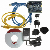
... Full C source code for the MCU firmware including TFTP bootloader. The software is also available for download from the Reference Design Kit CD and on the Figure 1. Power over Ethernet Voice Transmission Reference Design Board Rev. 0.2 9/ Silicon Laboratories Copyright © 2006 by Silicon Laboratories K U ’ website. PoE-VOICE-RD ...
Page 2
... PoE-VOICE-RD 2.1. Power Section The PoE-VoIP-EB Reference Design Board contains a Power Over Ethernet circuit based on the Si3400. In addition to performing all the functions required by the IEEE 802.3af specification, the Si3400 contains a switching regulator capable of regulating many voltages including 5 or 3.3 V. Since the Si3400 output will be passed through an LDO (used for the auxiliary 9 V supply output was chosen ...
Page 3
... Power can be injected into an Ethernet cable using an IEEE 802.3af compliant power injector such as the PHIHONG PSA16U-480. This power injector is widely available for approximately $25 from distributors such as Mouser Electronics at www.mouser.com Figure 2 shows an overview of Power Injection. 48V DC Network + Power Figure 2. Power Injection using PHIHONG PSA16U-480 or directly from PHIHONG at www.phihong.com. Network Only Rev. 0.2 PoE-VOICE-RD 100-240V AC 3 ...
Page 4
... PoE-VOICE-RD 4. Software Setup To get started, insert the CD-ROM into your PC’s CD-ROM drive. Follow the on-screen instructions when the blue dialog automatically launches. If the dialog does not automatically appear on the screen when you insert the CD- ROM, run autorun.exe found in the root directory of the CD-ROM. Select the installation for the Power Over Ethernet Voice Transmission Reference Design ...
Page 5
... PC with a static IP address and how to select a static IP address for the embedded system. Programming is successful when the status box displays the message “Succeeded!”. 5. Press Done when the assignment is complete. Then click View Data... on the main panel as shown in Figure 4. Figure 5. Assign IP Button Figure 6. Assign IP Button Rev. 0.2 PoE-VOICE-RD 5 ...
Page 6
... PoE-VOICE-RD 6. Power Over Ethernet Voice Transmission Demonstration The demonstration includes: Voice Transmission from the embedded system. Detecting PoE power vs. Auxiliary power. Monitoring real-time sensor data using a web browser. Controlling the state of the yellow and green LEDs from a web browser. Sending an e-mail from the embedded system containing the latest sensor data. ...
Page 7
... IEEE802.3af Power Source. While this procedure typically lasts less than 100 ms, it will cause a supply voltage dip large enough to trigger the built-in V CP2201. To provide seamless switching between power sources, a large valued capacitor may be used to keep the supply voltage constant during the switchover. PoE-VOICE-RD Monitors on both the 8051F340 and DD Rev. 0.2 ...
Page 8
... PoE-VOICE-RD 7. Power Over Ethernet Web Browser Demonstration Click on the Web Browser button. A web browser window should open and display a web page served from the embedded web server. This web page contains links to web server content stored in both the C8051F340 Main Flash and in the CP220x Flash Memory. Storing web server content in the CP220x Flash allows the MCU to utilize more of its executable Flash allowing more space for application firmware ...
Page 9
... The system has entered static IP address mode. Please use Netfinder to assign a static IP address or cycle power to continue searching for a DHCP server. Off (continuous) A hardware error has occurred. Please cycle power. Figure 11. Viewing Sensor Data Table 2. Yellow LED States System State Rev. 0.2 PoE-VOICE-RD 9 ...
Page 10
... PoE-VOICE-RD Clicking the second link on the main web page ‘2. Control Yellow LED’ will load the yellow LED control page shown in Figure 12. Each of the links numbered 1 through 4 on this page borrow the yellow and green LEDs for 10 seconds and force them to the state described in the text. The LED states are restored after 10 seconds or if the 5th link ‘ ...
Page 11
... Once the image location is specified, the command line TFTP client (standard on all Windows PCs) is launched and bootloading initiates. After seconds, a confirmation message will appear on the screen. Figure 15 shows an example of a confirmation message following a successful firmware update. Figure 15. Successful Firmware Update PoE-VOICE-RD Rev. 0.2 11 ...
Page 12
... PoE-VOICE-RD 12 Rev. 0.2 ...
Page 13
... PoE-VOICE-RD Rev. 0.2 13 ...
Page 14
... PoE-VOICE-RD 14 Rev. 0.2 ...
Page 15
... Schematics Vcc GND PoE-VOICE-RD Rev. 0.2 15 ...
Page 16
... PoE-VOICE- Rev. 0.2 ...
Page 17
... C26 0.1uF FB 20 R16 2.67K VSS2 19 SWO 18 C25 1.0uF VSS1 17 C32 10u Vposs 16 C11 1.0uF SNUB 15 C29 1.0uF VC+ anode LED2 V+ 15 Cath LED1 V- 14 anode LED1 VC- 13 cath LED1 12 PoE-VOICE-RD 1 PLOSSb 5 RDET 6 HSO 7 48.7 R13 RCL 8 Vneg 9 SP2 Rev. 0.2 17 ...
Page 18
... PoE-VOICE-RD A —U C PPENDIX SING A Introduction The PoE-VOICE-EB can be connected to an Ethernet network using a standard Ethernet cable (see Figure 19) or directly using a crossover cable (see Figure 20). Table 4 describes the benefits of using each of the connection methods. A standard Ethernet cable is included in the kit and crossover cables are available for order from the Silicon Laboratories website, at www ...
Page 19
... If entering a one or two digit octet, the spacebar, right arrow key, or ‘.’ can be pressed to advance to the next field. Figure 22. IP Address and Subnet Mask Window 5. Click OK after the static IP address and subnet mask have been configured. The PC will now be able to access the embedded system using a crossover cable. PoE-VOICE-RD Rev. 0.2 19 ...
Page 20
... PoE-VOICE-RD Selecting an IP Address for the Embedded System For recognize an embedded system on a network, its IP address and subnet mask need to be configured. Below are a few guidelines to follow when choosing an IP address for the embedded system. Figure 23 shows an example of a compatible PC and embedded system IP address combination. ...
Page 21
... N : OTES PoE-VOICE-RD Rev. 0.2 21 ...
Page 22
... PoE-VOICE- ONTACT NFORMATION Silicon Laboratories Inc. 400 West Cesar Chavez Austin, TX 78701 Email: MCUinfo@silabs.com Internet: www.silabs.com The information in this document is believed to be accurate in all respects at the time of publication but is subject to change without notice. Silicon Laboratories assumes no responsibility for errors and omissions, and disclaims responsibility for any consequences resulting from the use of information included herein ...