MAX3421EVKIT-1+ Maxim Integrated Products, MAX3421EVKIT-1+ Datasheet - Page 4
MAX3421EVKIT-1+
Manufacturer Part Number
MAX3421EVKIT-1+
Description
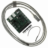
EVAL KIT FOR MAX3421E
Manufacturer
Maxim Integrated Products
Datasheet
1.MAX3421EVKIT-1.pdf
(9 pages)
Specifications of MAX3421EVKIT-1+
Main Purpose
Interface, USB 2.0 Host/Controller
Embedded
Yes, MCU, 8-Bit
Utilized Ic / Part
MAX3421E
Primary Attributes
Full Speed (12Mbps), SPI Interface
Secondary Attributes
MAX3420E Provided On-Board as a Test Peripheral
Lead Free Status / RoHS Status
Lead free / RoHS Compliant


Table 1. J4 Interface to the MAX3420E and MAX3421E
1) The MAX3420E connects to USB Type B connector
2) The user system must supply 3.3V on J4 pins 1-2 to
3) The RES pins connect directly to the MAX3420E/
4) When operating the MAX3421E as a host controller,
MAX3421 Evaluation Kit-1
4
J5, while the MAX3421E connects both to USB Type
A connector J1 and to USB Type B connector J2.
The MAX3421E, therefore, can be connected as a
host (J1) or a peripheral (J2).
power the board. The 3.3V supply should be capa-
ble of providing 100mA.
MAX3421E reset pins. It must be driven high for the
chip to operate.
the user system must provide 5V power on J4 pins
33-34, or on J3 pin 3. This voltage connects to the
V
current-limiting switch. The user system must supply
_______________________________________________________________________________________
BUS
J4 PIN
10
11
12
13
14
15
16
17
18
1
2
3
4
5
6
7
8
9
pin of USB Type A connector J1 through a
MAX3420E
MISO (out)
GPX (out)
MOSI (in)
3.3V (in)
SCK (in)
RES (in)
SS (in)
—
—
—
—
—
—
—
—
—
—
—
User Notes:
MAX3421E
MISO (out)
3.3V (in)
SCK (in)
RES (in)
—
—
—
—
—
—
—
—
—
—
—
—
—
—
5) Keep leads to the target system short (under 6in).
6) When using the MAX3421E as a host, the user
enough current to power any USB device plugged
into J1. The current-limiting switch (a MAX4793) lim-
its the V
Long leads and insufficient grounds can lead to sig-
nal ringing and erratic operation.
program must set the MAX3421E GPO7 pin high
to turn on the V
the USB Type A connector J1. Note that the
MAX3421E output port also drives the 7-segment
readout using GPO[6:0]. Therefore, the code that
updates the 7-segment readout must preserve the
bit 7 setting, and the code that turns V
off must preserve the bits [6:0] settings. This is easi-
ly accomplished by first reading the states of the
output bits, changing only the needed bits, then
writing them back.
J4 PIN
19
20
21
22
23
24
25
26
27
28
29
30
31
32
33
34
35
36
BUS
current to 300mA.
BUS
MAX3420E
switch (U3) that supplies 5V to
INT (out)
GND
GND
—
—
—
—
—
—
—
—
—
—
—
—
—
—
—
MAX3421E
MISO (out)
GPX (out)
MOSI (in)
INT (out)
SCK (in)
BUS
SS (in)
5V (in)
5V (in)
GND
GND
—
—
—
—
—
—
—
—
on and
Related parts for MAX3421EVKIT-1+
Image
Part Number
Description
Manufacturer
Datasheet
Request
R

Part Number:
Description:
USB Peripheral/Host Controller
Manufacturer:
Maxim Integrated Products
Datasheet:
Part Number:
Description:
MAX7528KCWPMaxim Integrated Products [CMOS Dual 8-Bit Buffered Multiplying DACs]
Manufacturer:
Maxim Integrated Products
Datasheet:
Part Number:
Description:
Single +5V, fully integrated, 1.25Gbps laser diode driver.
Manufacturer:
Maxim Integrated Products
Datasheet:
Part Number:
Description:
Single +5V, fully integrated, 155Mbps laser diode driver.
Manufacturer:
Maxim Integrated Products
Datasheet:
Part Number:
Description:
VRD11/VRD10, K8 Rev F 2/3/4-Phase PWM Controllers with Integrated Dual MOSFET Drivers
Manufacturer:
Maxim Integrated Products
Datasheet:
Part Number:
Description:
Highly Integrated Level 2 SMBus Battery Chargers
Manufacturer:
Maxim Integrated Products
Datasheet:
Part Number:
Description:
Current Monitor and Accumulator with Integrated Sense Resistor; ; Temperature Range: -40°C to +85°C
Manufacturer:
Maxim Integrated Products
Part Number:
Description:
TSSOP 14/A�/RS-485 Transceivers with Integrated 100O/120O Termination Resis
Manufacturer:
Maxim Integrated Products
Part Number:
Description:
TSSOP 14/A�/RS-485 Transceivers with Integrated 100O/120O Termination Resis
Manufacturer:
Maxim Integrated Products
Part Number:
Description:
QFN 16/A�/AC-DC and DC-DC Peak-Current-Mode Converters with Integrated Step
Manufacturer:
Maxim Integrated Products
Part Number:
Description:
TDFN/A/65V, 1A, 600KHZ, SYNCHRONOUS STEP-DOWN REGULATOR WITH INTEGRATED SWI
Manufacturer:
Maxim Integrated Products
Part Number:
Description:
Integrated Temperature Controller f
Manufacturer:
Maxim Integrated Products
Part Number:
Description:
SOT23-6/I�/45MHz to 650MHz, Integrated IF VCOs with Differential Output
Manufacturer:
Maxim Integrated Products
Part Number:
Description:
SOT23-6/I�/45MHz to 650MHz, Integrated IF VCOs with Differential Output
Manufacturer:
Maxim Integrated Products
Part Number:
Description:
EVALUATION KIT/2.4GHZ TO 2.5GHZ 802.11G/B RF TRANSCEIVER WITH INTEGRATED PA
Manufacturer:
Maxim Integrated Products