CDB5376 Cirrus Logic Inc, CDB5376 Datasheet - Page 31
CDB5376
Manufacturer Part Number
CDB5376
Description
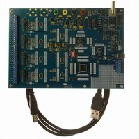
EVALUATION BOARD FOR CS5376
Manufacturer
Cirrus Logic Inc
Datasheets
1.CS5371A-ISZR.pdf
(32 pages)
2.CS4373A-ISZ.pdf
(34 pages)
3.CS5376A-IQZR.pdf
(106 pages)
4.CDB5378.pdf
(16 pages)
5.CDB5376.pdf
(80 pages)
6.CDB5376.pdf
(16 pages)
Specifications of CDB5376
Main Purpose
Seismic Evaluation System
Embedded
Yes, MCU, 8-Bit
Utilized Ic / Part
CS3301A, CS3302A, CS4373A, CS5372A, CS5376A
Primary Attributes
Quad Digital Filter
Secondary Attributes
Graphical User Interface, SPI™ & USB Interfaces
Processor To Be Evaluated
CS330x, CS4373A, CS537x
Interface Type
USB
Lead Free Status / RoHS Status
Contains lead / RoHS non-compliant
Lead Free Status / RoHS Status
Lead free / RoHS Compliant, Contains lead / RoHS non-compliant
Other names
598-1778


2.3.6
By default, CDB5376 communicates with the PC evaluation software through the microcontroller USB
port. Additional hardware is designed onto CDB5376 to use the microcontroller I
local telemetry, but it is provided for custom programming convenience only and is not directly supported
by the CDB5376 PC evaluation software or microcontroller firmware.
Telemetry signals enter CDB5376 through RS-485 transceivers, which are differential current mode trans-
ceivers that can reliably drive long distance communication. Data passes through the RS-485 transceiv-
ers to the microcontroller I
2.3.6.1
Clock and synchronization telemetry signals into CDB5376 are received through RS-485 twisted pairs.
These signals are required to be distributed through the external system with minimal jitter and timing
skew, and so are normally driven through high-speed bus connections.
Synchronization of the measurement channel is critical to ensure simultaneous analog sampling across
a network. Several options are available for connecting a SYNC signal through the RS-485 telemetry to
the digital filter.
A direct connection is made when the SYNC_IO signal is received over the dedicated RS-485 twisted pair
and sent directly to the digital filter SYNC pin through jumper J56. The incoming SYNC_IO signal must be
synchronized to the network at the transmitter since no local timing adjustment is available.
A microcontroller hardware connection is made when the SYNC_IO signal is received over the dedicated
RS-485 twisted pair and detected by a microcontroller interrupt. The microcontroller can then use an in-
ternal counter to re-time the SYNC_MC signal output to the digital filter SYNC input as required.
DS612DB3
Specification
RS-485 Transceiver - Linear Tech
Surface Mount Package Type
Supply Voltage, Quiescent Current
Maximum Data Rate
Transmitter Delay, Receiver Delay
Transmitter Current, Full Termination (60 Ω)
Transmitter Current, Half Termination (120 Ω)
Specification
Synchronous Inputs, 2 wires each
Specification
Distributed SYNC Signal Synchronization
Distributed Clock Synchronization
Analog Sampling Synchronization Accuracy
RS-485 Telemetry
CLK, SYNC
2
C interface and the clock and synchronization inputs.
Value
LTC1480IS8
SOIC-8, 5mm x 6mm
3.3V, 600 µA
2.5 Mbps
25 - 80 ns, 30 - 200 ns
25 mA
13 mA
Value
CLK±, SYNC±
Value
± 240 ns
± 240 ns
± 480 ns
2
C
®
port as a low-level
CDB5376
31
Related parts for CDB5376
Image
Part Number
Description
Manufacturer
Datasheet
Request
R

Part Number:
Description:
Development Kit
Manufacturer:
Cirrus Logic Inc
Datasheet:
Part Number:
Description:
Development Kit
Manufacturer:
Cirrus Logic Inc
Datasheet:


Part Number:
Description:
High-efficiency PFC + Fluorescent Lamp Driver Reference Design
Manufacturer:
Cirrus Logic Inc
Datasheet:
Part Number:
Description:
Development Kit
Manufacturer:
Cirrus Logic Inc
Datasheet:
Part Number:
Description:
Development Kit
Manufacturer:
Cirrus Logic Inc
Datasheet:

Part Number:
Description:
Development Kit
Manufacturer:
Cirrus Logic Inc
Datasheet:
Part Number:
Description:
Development Kit
Manufacturer:
Cirrus Logic Inc
Datasheet:
Part Number:
Description:
Development Kit
Manufacturer:
Cirrus Logic Inc
Datasheet:
Part Number:
Description:
Development Kit
Manufacturer:
Cirrus Logic Inc
Datasheet:

Part Number:
Description:
EVALUATION BOARD FOR CS8427
Manufacturer:
Cirrus Logic Inc
Datasheet:

Part Number:
Description:
BOARD EVAL FOR CS8416 RCVR
Manufacturer:
Cirrus Logic Inc
Datasheet:

Part Number:
Description:
EVALUATION BOARD FOR CS8420
Manufacturer:
Cirrus Logic Inc
Datasheet:

Part Number:
Description:
KIT DEVELOPMENT EP9315 ARM9
Manufacturer:
Cirrus Logic Inc
Datasheet:

Part Number:
Description:
KIT DEVELOPMENT EP9302 ARM9
Manufacturer:
Cirrus Logic Inc
Datasheet: