STEVAL-IHM010V1 STMicroelectronics, STEVAL-IHM010V1 Datasheet - Page 41
STEVAL-IHM010V1
Manufacturer Part Number
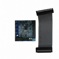
STEVAL-IHM010V1
Description
KIT IGBT PWR MODULE CTRL ST7MC
Manufacturer
STMicroelectronics
Type
Motor / Motion Controllers & Driversr
Specifications of STEVAL-IHM010V1
Main Purpose
Power Management, Motor Control
Embedded
Yes, MCU, 8-Bit
Utilized Ic / Part
ST7FMC2S4
Primary Attributes
3-Ph Brushless BLDC, AC & 3-Ph AC Induction (ACIM) Motors
Secondary Attributes
Graphic User Interface, 4 Pots for Runtime Settings, Start/Stop and Reset Buttons
Input Voltage
5 V
Product
Power Management Modules
Silicon Manufacturer
ST Micro
Core Architecture
ARM
Core Sub-architecture
ARM7TDMI
Silicon Core Number
ST7
Silicon Family Name
ST7MCx
Kit Contents
Board
Lead Free Status / RoHS Status
Lead free / RoHS Compliant
For Use With/related Products
ST7MC
Other names
497-8400


UM0430
7.7.1
7.7.2
7.7.3
7.7.4
7.7.5
set up for voltage mode - open loop - sensor 60° driving (see
BLAC/DC (trapezoidal)"
Specific connection (sensor)
To drive the motor, the motor must have three position sensors, in this case three hall
sensors. For this demonstration we suggest using one Ametek BLDC Blower motor (voltage
max 30 Vdc).
Refer to the descriptions in
Table 15.
Specific jumper settings
To set up the power board jumper, follow the instructions in the power board user manual for
driving the BLDC motor (trapezoidal - sensored). Close the J5 jumper on the control board
between pin 2-3. Keep J2 of the control board open.
LED behavior after power on
Turn on the power supply. For this demonstration the power supply output voltage should be
set to 30 Vdc and current limitation of the power supply should be set to 4 amp. After power
on, the control board LED behavior should be the following:
●
●
Setting of potentiometer
●
●
●
Running the motor (LED behavior)
Push the start/stop button. After pushing the button the LEDs toggle from green to red to
indicate "run state". The motor starts to run.
Red LEDs blink signaling that the firmware has started to run.
After a while a green LED stays on to indicate "idle state"
Set P1 potentiometer in middle position from full counter clockwise to full clockwise.
Set P2 potentiometer in full clockwise position.
Set P3 potentiometer in full clockwise position.
"BLDC Sensored" motor connections
Hall sensor +5 V (red)
Hall sensor 2 (green)
Hall sensor 1 (white)
Hall sensor 3 (blue)
Hall ground (black)
Phase B (yellow)
Phase C (black)
Phase A (red)
Motor
settings).
Table 15
to connect the motor to the power board.
Motor control demonstration
Section 7.4.4: "3 Phase
Power board
J4 pin 1
J4 pin 2
J4 pin 3
J1 pin 1
J1 pin 2
J1 pin 3
J1 pin 4
J1 pin 5
41/48
Related parts for STEVAL-IHM010V1
Image
Part Number
Description
Manufacturer
Datasheet
Request
R

Part Number:
Description:
BOARD EVAL FOR MEMS SENSORS
Manufacturer:
STMicroelectronics
Datasheet:

Part Number:
Description:
KIT DEV STARTER ST10F276Z5
Manufacturer:
STMicroelectronics
Datasheet:

Part Number:
Description:
BOARD EVAL HDMI $ VIDEO SWITCH
Manufacturer:
STMicroelectronics
Datasheet:

Part Number:
Description:
BOARD DEMO ACCELEROMETER DIL24
Manufacturer:
STMicroelectronics
Datasheet:

Part Number:
Description:
BOARD STLM75/STDS75/ST72F651
Manufacturer:
STMicroelectronics
Datasheet:

Part Number:
Description:
EVAL BOARD 3AXIS MEMS ACCELLRMTR
Manufacturer:
STMicroelectronics
Datasheet:

Part Number:
Description:
BOARD EVAL 8BIT MICRO + TDE1708
Manufacturer:
STMicroelectronics
Datasheet:

Part Number:
Description:
EVAL BOARD A/D TS4657
Manufacturer:
STMicroelectronics
Datasheet:

Part Number:
Description:
BOARD ADAPTER 20DIP LIS3LV02DL
Manufacturer:
STMicroelectronics
Datasheet:

Part Number:
Description:
BOARD DEMO STM8S207R6/LIS331DLH
Manufacturer:
STMicroelectronics
Datasheet:

Part Number:
Description:
STMicroelectronics [RIPPLE-CARRY BINARY COUNTER/DIVIDERS]
Manufacturer:
STMicroelectronics
Datasheet:
Part Number:
Description:
STMicroelectronics [LIQUID-CRYSTAL DISPLAY DRIVERS]
Manufacturer:
STMicroelectronics
Datasheet:
Part Number:
Description:
BOARD EVAL FOR MEMS SENSORS
Manufacturer:
STMicroelectronics
Datasheet: