STEVAL-IHM010V1 STMicroelectronics, STEVAL-IHM010V1 Datasheet - Page 42
STEVAL-IHM010V1
Manufacturer Part Number
STEVAL-IHM010V1
Description
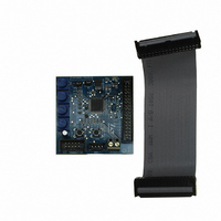
KIT IGBT PWR MODULE CTRL ST7MC
Manufacturer
STMicroelectronics
Type
Motor / Motion Controllers & Driversr
Specifications of STEVAL-IHM010V1
Main Purpose
Power Management, Motor Control
Embedded
Yes, MCU, 8-Bit
Utilized Ic / Part
ST7FMC2S4
Primary Attributes
3-Ph Brushless BLDC, AC & 3-Ph AC Induction (ACIM) Motors
Secondary Attributes
Graphic User Interface, 4 Pots for Runtime Settings, Start/Stop and Reset Buttons
Input Voltage
5 V
Product
Power Management Modules
Silicon Manufacturer
ST Micro
Core Architecture
ARM
Core Sub-architecture
ARM7TDMI
Silicon Core Number
ST7
Silicon Family Name
ST7MCx
Kit Contents
Board
Lead Free Status / RoHS Status
Lead free / RoHS Compliant
For Use With/related Products
ST7MC
Other names
497-8400


Motor control demonstration
7.7.6
Table 16.
42/48
P1
P2 sets the value of rising delay coefficient from 0 to 255
P3 sets the value of falling delay coefficient from 0 to 255 sets the value of falling delay coefficient from 0 to 255
P4
P1
P2 sets the value of rising delay coefficient from 0 to 255
P3 sets the value of falling delay coefficient from 0 to 255 sets the value of falling delay coefficient from 0 to 255
P4
sets the current reference value from 0 A to maximum
sets the duty cycle percentage from 0% to 100%.
15
During any state: idle, start, run or brake, if the red LED stays on along with the brake of the
motor, this indicates a fault condition. A fault condition is due to one of the following
conditions:
●
●
●
●
●
Blinking of the red LED during the running of the motor indicates that software current
limitation is in action.
Changing real-time parameters
The real-time parameters can be changed using the potentiometers of the control board.
Table 16
Potentiometer functionality based on open/closed loop driving strategy
If during the configuration using GUI, the "from RV1" control has been unchecked, the
value of duty cycle (or the value of current reference) is not set by P1, but has a fixed value.
If during the configuration using GUI, the "From RV2 - RV3" control has been unchecked,
the value of the rising delay coefficient and the value of the falling delay coefficient are not
set by P2 and P3, but have fixed values.
Hardware overcurrent: current flowing inside motor reaches a value greater than max
current allowed 4.1 amp (see
by
Over voltage: bus voltage reaches a value greater than 280 Vac.
Over temperature: onboard temperature sensor measures a temperature greater than
60°.
Startup failed: startup phase ends without getting a sufficient number of valid zero
crossing events.
Motor stalled: during the run of the motor no other zero crossing events have been
observed.
GUI)
current allowed.
explains the potentiometer functionality based on the driving strategy.
Open loop
Open loop
not used
not used
Current mode
Voltage mode
Section 7.4.10: Changing the maximum current allowed
value to maximum value configured (see
value to Maximum value configured (see
sets the value of rising delay coefficient from 0 to 255
sets the value of rising delay coefficient from 0 to 255
sets the target rotor frequency value from minimum
sets the target rotor frequency value from minimum
"3 Phase BLAC/DC (trapezoidal)"
"3 Phase BLAC/DC (trapezoidal)"
Closed loop
Closed loop
not used
not used
settings)
settings)
Section 7.4.4:
Section 7.4.4:
UM0430
Related parts for STEVAL-IHM010V1
Image
Part Number
Description
Manufacturer
Datasheet
Request
R

Part Number:
Description:
BOARD EVAL FOR MEMS SENSORS
Manufacturer:
STMicroelectronics
Datasheet:

Part Number:
Description:
KIT DEV STARTER ST10F276Z5
Manufacturer:
STMicroelectronics
Datasheet:

Part Number:
Description:
BOARD EVAL HDMI $ VIDEO SWITCH
Manufacturer:
STMicroelectronics
Datasheet:

Part Number:
Description:
BOARD DEMO ACCELEROMETER DIL24
Manufacturer:
STMicroelectronics
Datasheet:

Part Number:
Description:
BOARD STLM75/STDS75/ST72F651
Manufacturer:
STMicroelectronics
Datasheet:

Part Number:
Description:
EVAL BOARD 3AXIS MEMS ACCELLRMTR
Manufacturer:
STMicroelectronics
Datasheet:

Part Number:
Description:
BOARD EVAL 8BIT MICRO + TDE1708
Manufacturer:
STMicroelectronics
Datasheet:

Part Number:
Description:
EVAL BOARD A/D TS4657
Manufacturer:
STMicroelectronics
Datasheet:

Part Number:
Description:
BOARD ADAPTER 20DIP LIS3LV02DL
Manufacturer:
STMicroelectronics
Datasheet:

Part Number:
Description:
BOARD DEMO STM8S207R6/LIS331DLH
Manufacturer:
STMicroelectronics
Datasheet:

Part Number:
Description:
STMicroelectronics [RIPPLE-CARRY BINARY COUNTER/DIVIDERS]
Manufacturer:
STMicroelectronics
Datasheet:
Part Number:
Description:
STMicroelectronics [LIQUID-CRYSTAL DISPLAY DRIVERS]
Manufacturer:
STMicroelectronics
Datasheet:
Part Number:
Description:
BOARD EVAL FOR MEMS SENSORS
Manufacturer:
STMicroelectronics
Datasheet: