CP2201EK Silicon Laboratories Inc, CP2201EK Datasheet - Page 18
CP2201EK
Manufacturer Part Number
CP2201EK
Description
KIT EVAL FOR CP2201 ETH CTRLR
Manufacturer
Silicon Laboratories Inc
Type
Controllers & Processorsr
Specifications of CP2201EK
Main Purpose
Interface, Ethernet Sensor
Embedded
Yes, MCU, 8-Bit
Utilized Ic / Part
CP2200, CP2201
Primary Attributes
Temperature and Light Sensor
Secondary Attributes
Graphic User Interface
Interface Type
Ethernet
Product
Modules
Silicon Manufacturer
Silicon Labs
Silicon Core Number
CP2201
Silicon Family Name
CP220x
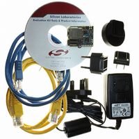
Kit Contents
CP2201 Evaluation Board, Power Adapter, CAT5e Ethernet Cable, CD-ROM, Quick-Start Guide
For Use With/related Products
CP2201
Lead Free Status / RoHS Status
Contains lead / RoHS non-compliant
Lead Free Status / RoHS Status
Lead free / RoHS Compliant, Contains lead / RoHS non-compliant
Other names
336-1316
Available stocks
Company
Part Number
Manufacturer
Quantity
Price
Company:

Part Number:
CP2201EK
Manufacturer:
SiliconL
Quantity:
8


CP2200/1
6. Functional Description
6.1. Overview
In most systems, the CP2200/1 is used for transmitting and receiving Ethernet packets, non-volatile data storage,
and controlling Link and Activity LEDs. The device is controlled using direct and indirect internal registers
accessible through the parallel host interface. All digital pins on the device are 5 V tolerant.
6.2. Reset Initialization
After every CP2200/1 reset, the following initialization procedure is recommended to ensure proper device
operation:
6.3. Interrupt Request Signal
The CP2200/1 has an interrupt request signal (INT) that can be used to notify the host processor of pending
interrupts. The INT signal is asserted upon detection of any enabled interrupt event. Host processors that cannot
dedicate a port pin to the INT signal can periodically poll the interrupt status registers to see if any interrupt
generating events have occurred. If the /INT signal is not used, pending interrupts such a Receive FIFO Full must
still be serviced.
The 14 interrupt sources are listed below. Interrupts are enabled on reset and can be disabled by software.
Pending interrupts can be cleared (allowing the INT signal to de-assert) by reading the self-clearing interrupt
registers. See “8. Interrupt Sources” on page 30 for a complete description of the CP2200/1 interrupts.
18
End of Packet Reached
Receive FIFO Empty
Receive FIFO Full
Oscillator Initialization Complete
Self Initialization Complete
Flash Write/Erase Complete
Packet Transmitted
Step 1: Wait for the reset pin to rise. This step takes the longest during a power-on reset.
Step 2: Wait for Oscillator Initialization to complete. The host processor will receive notification through the
Step 3: Wait for Self Initialization to complete. The INT0 interrupt status register on page 31 should be
Step 4: Disable interrupts (using INT0EN and INT1EN on page 33 and page 36) for events that will not be
Step 5: Initialize the physical layer. See “15.7. Initializing the Physical Layer” on page 90 for a detailed
Step 6: Enable the desired Activity, Link, or Activity/Link LEDs using the IOPWR register on page 45.
Step 7: Initialize the media access controller (MAC). See “14.1. Initializing the MAC” on page 78 for a
Step 8: Configure the receive filter. See “12.4. Initializing the Receive Buffer, Filter and Hash Table” on
Step 9: The CP2200/1 is ready to transmit and receive packets.
interrupt request signal once the oscillator has stabilized.
checked to determine when Self Initialization completes.
monitored or handled by the host processor. By default, all interrupts are enabled after every reset.
physical layer initialization procedure.
detailed MAC initialization procedure.
page 59 for a detailed initialization procedure.
Rev. 1.0
Packet Received
“Wake-on-LAN” Wakeup Event
Link Status Changed
Jabber Detected
Auto-Negotiation Failed
Remote Fault Notification
Auto-Negotiation Complete
Related parts for CP2201EK
Image
Part Number
Description
Manufacturer
Datasheet
Request
R

Part Number:
Description:
IC ETH CTRLR SNGL-CHIP 28QFN
Manufacturer:
Silicon Laboratories Inc
Datasheet:

Part Number:
Description:
Ethernet ICs Ethernet Controller
Manufacturer:
Silicon Laboratories Inc

Part Number:
Description:
SMD/C°/SINGLE-ENDED OUTPUT SILICON OSCILLATOR
Manufacturer:
Silicon Laboratories Inc
Part Number:
Description:
Manufacturer:
Silicon Laboratories Inc
Datasheet:
Part Number:
Description:
N/A N/A/SI4010 AES KEYFOB DEMO WITH LCD RX
Manufacturer:
Silicon Laboratories Inc
Datasheet:
Part Number:
Description:
N/A N/A/SI4010 SIMPLIFIED KEY FOB DEMO WITH LED RX
Manufacturer:
Silicon Laboratories Inc
Datasheet:
Part Number:
Description:
N/A/-40 TO 85 OC/EZLINK MODULE; F930/4432 HIGH BAND (REV E/B1)
Manufacturer:
Silicon Laboratories Inc
Part Number:
Description:
EZLink Module; F930/4432 Low Band (rev e/B1)
Manufacturer:
Silicon Laboratories Inc
Part Number:
Description:
I°/4460 10 DBM RADIO TEST CARD 434 MHZ
Manufacturer:
Silicon Laboratories Inc
Part Number:
Description:
I°/4461 14 DBM RADIO TEST CARD 868 MHZ
Manufacturer:
Silicon Laboratories Inc
Part Number:
Description:
I°/4463 20 DBM RFSWITCH RADIO TEST CARD 460 MHZ
Manufacturer:
Silicon Laboratories Inc
Part Number:
Description:
I°/4463 20 DBM RADIO TEST CARD 868 MHZ
Manufacturer:
Silicon Laboratories Inc
Part Number:
Description:
I°/4463 27 DBM RADIO TEST CARD 868 MHZ
Manufacturer:
Silicon Laboratories Inc
Part Number:
Description:
I°/4463 SKYWORKS 30 DBM RADIO TEST CARD 915 MHZ
Manufacturer:
Silicon Laboratories Inc