CP2201EK Silicon Laboratories Inc, CP2201EK Datasheet - Page 23
CP2201EK
Manufacturer Part Number
CP2201EK
Description
KIT EVAL FOR CP2201 ETH CTRLR
Manufacturer
Silicon Laboratories Inc
Type
Controllers & Processorsr
Specifications of CP2201EK
Main Purpose
Interface, Ethernet Sensor
Embedded
Yes, MCU, 8-Bit
Utilized Ic / Part
CP2200, CP2201
Primary Attributes
Temperature and Light Sensor
Secondary Attributes
Graphic User Interface
Interface Type
Ethernet
Product
Modules
Silicon Manufacturer
Silicon Labs
Silicon Core Number
CP2201
Silicon Family Name
CP220x
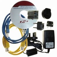
Kit Contents
CP2201 Evaluation Board, Power Adapter, CAT5e Ethernet Cable, CD-ROM, Quick-Start Guide
For Use With/related Products
CP2201
Lead Free Status / RoHS Status
Contains lead / RoHS non-compliant
Lead Free Status / RoHS Status
Lead free / RoHS Compliant, Contains lead / RoHS non-compliant
Other names
336-1316
Available stocks
Company
Part Number
Manufacturer
Quantity
Price
Company:

Part Number:
CP2201EK
Manufacturer:
SiliconL
Quantity:
8


7. Internal Memory and Registers
The CP2200/1 is controlled through direct and indirect registers accessible through the parallel host interface. The
host interface provides an 8-bit address space, of which there are 114 valid direct register locations (see Table 11
on page 25). All remaining addresses in the memory space are reserved and should not be read or written. The
direct registers provide access to the RAM buffers, Flash memory, indirect MAC configuration registers, and other
status and control registers for various device functions.
Figure 13 shows the RAM and Flash memory organization. The transmit and receive RAM buffers share the same
address space and are both accessed using the RAMADDRH:RAMADDRL pointer. Each of the buffers has a
dedicated data register. The Flash memory has a separate address space and a dedicated address pointer and
data register. See “13. Flash Memory” on page 73 for detailed information on how to read and write to Flash.
7.1. Random Access to RAM Transmit and Receive Buffers
The most common and most efficient methods for accessing the transmit and receive buffers are the AutoWrite
and AutoRead interfaces. These interfaces allow entire packets to be written or read at a time. In very few cases,
the transmit and receive buffers may need to be accessed randomly. An example of this is a system in which a
specific byte in the packet is checked to determine whether to read the packet or discard it. The following
procedure can be used to read or write data to either RAM buffer:
Transmit Buffer (2K)
0x0000 – 0x07FF
Step 1: Write the address of the target byte to RAMADDRH:RAMADDRL.
Step 2: Transmit Buffer:
Read or write 8-bit data to RAMTXDATA to read or write from the target byte in the transmit buffer.
Receive Buffer:
Read or write 8-bit data to RAMRXDATA to read or write from the target byte in the receive buffer.
Note: Reads and writes of the RAM buffers using the random access method are independent of the
AutoRead and AutoWrite interfaces. Each of the interfaces has a dedicated set of address and data
registers. See “11.2. Transmitting a Packet” on page 48 and “12.2. Reading a Packet Using the
Autoread Interface” on page 58 for additional information about the AutoRead and AutoWrite
interfaces.
Figure 13. RAM Buffers and Flash Memory Organization
RAMADDRH:RAMADDRL
Receive Buffer (4K)
0x0000 – 0x0FFF
Rev. 1.0
FLASHADDRH:FLASHADDRL
Flash Memory (8K)
0x0000 – 0x1FFF
CP2200/1
23
Related parts for CP2201EK
Image
Part Number
Description
Manufacturer
Datasheet
Request
R

Part Number:
Description:
IC ETH CTRLR SNGL-CHIP 28QFN
Manufacturer:
Silicon Laboratories Inc
Datasheet:

Part Number:
Description:
Ethernet ICs Ethernet Controller
Manufacturer:
Silicon Laboratories Inc

Part Number:
Description:
SMD/C°/SINGLE-ENDED OUTPUT SILICON OSCILLATOR
Manufacturer:
Silicon Laboratories Inc
Part Number:
Description:
Manufacturer:
Silicon Laboratories Inc
Datasheet:
Part Number:
Description:
N/A N/A/SI4010 AES KEYFOB DEMO WITH LCD RX
Manufacturer:
Silicon Laboratories Inc
Datasheet:
Part Number:
Description:
N/A N/A/SI4010 SIMPLIFIED KEY FOB DEMO WITH LED RX
Manufacturer:
Silicon Laboratories Inc
Datasheet:
Part Number:
Description:
N/A/-40 TO 85 OC/EZLINK MODULE; F930/4432 HIGH BAND (REV E/B1)
Manufacturer:
Silicon Laboratories Inc
Part Number:
Description:
EZLink Module; F930/4432 Low Band (rev e/B1)
Manufacturer:
Silicon Laboratories Inc
Part Number:
Description:
I°/4460 10 DBM RADIO TEST CARD 434 MHZ
Manufacturer:
Silicon Laboratories Inc
Part Number:
Description:
I°/4461 14 DBM RADIO TEST CARD 868 MHZ
Manufacturer:
Silicon Laboratories Inc
Part Number:
Description:
I°/4463 20 DBM RFSWITCH RADIO TEST CARD 460 MHZ
Manufacturer:
Silicon Laboratories Inc
Part Number:
Description:
I°/4463 20 DBM RADIO TEST CARD 868 MHZ
Manufacturer:
Silicon Laboratories Inc
Part Number:
Description:
I°/4463 27 DBM RADIO TEST CARD 868 MHZ
Manufacturer:
Silicon Laboratories Inc
Part Number:
Description:
I°/4463 SKYWORKS 30 DBM RADIO TEST CARD 915 MHZ
Manufacturer:
Silicon Laboratories Inc