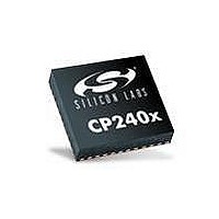
CP2400AB Silicon Laboratories Inc, CP2400AB Datasheet - Page 23

CP2400AB
Manufacturer Part Number
CP2400AB
Description
BOARD EVAL SPI LCD DRIVER CP2400
Manufacturer
Silicon Laboratories Inc
Specifications of CP2400AB
Main Purpose
LCD Development
Embedded
No
Utilized Ic / Part
CP2400
Primary Attributes
I²C, SMBus Interfaces
Secondary Attributes
Up to 128 segments
Product
Microcontroller Accessories
Core Processor
CP2400
Clock Speed
20 MHz
Interface Type
SPI
Timers
2
Operating Supply Voltage
1.8 V to 3.6 V
Cpu Core
CP2400
Lead Free Status / RoHS Status
Contains lead / RoHS non-compliant
Lead Free Status / RoHS Status
Lead free / RoHS Compliant, Contains lead / RoHS non-compliant
Other names
336-1857
8.2. AB Board Current Measurement
The header (J2) provides a way to measure the total supply current flowing from the power supply source to the
CP2400/1. The measured current does not include any current from the LED (D1) or the Power LED (D2). See the
target board schematics in Figures 15 through 18 for additional information.
8.3. Port I/O Headers (J1, J3)
Access to the CP2400/1 control interface signals (SMBus or SPI) as well as /RST, /LED, /INT, /CLK, VDD, and
GND is provided through J1 on the AB board. The header J3 provides access to the ground plane for easy clipping
of oscilloscope probes.
8.4. LEDs
Two LEDs are provided on the AB board: one labeled “LED” and one labeled “PWR”. The PWR LED is powered by
VDD being supplied to the CP2400/1. The other LED labeled “LED” is powered through from P1.7 on the
C8051F930 Target Board or P2.7 on the C8051F912 Target Board. Tables 6 and 7 contain more information
regarding which port pins’ control signals are connected to on the target board. Headers are provided on the AB
board to allow for the LEDs to be physically disconnected from the circuit. Placing a jumper on the header J4 will
connect the PWR LED to ground, which will allow it to turn on when a voltage is applied on the CP2400/1’s VDD
pin. Placing a jumper on the header J5 will connect LED labeled LED to the LED signal on the attached Target
Board. Tables 6 and 7 list information on which port pin on the attached Target Board is connected to the LED
signal. The CP2400 LCD Development Board schematic and the CP2401 LCD Development Board schematic
have more information about the LED and control signals.
8.5. Target Board Connections
Tables 6 and 7 list details regarding the port pin connections to the control signals on the CP2400/1.
Signal
Signal
/PWR
MISO
MOSI
/RST
/CLK
/LED
/RST
/CLK
/LED
SCK
NSS
SDA
/INT
SCL
/INT
Table 6. CP2400 Control Signals
Table 7. CP2401 Control Signals
F930 TB
F930 TB
P1.0
P1.1
P1.2
P1.3
P0.1
P0.0
P1.4
P1.7
P1.0
P1.1
P1.3
P0.1
P0.0
P1.4
P1.7
Rev. 0.1
F912 TB
F912 TB
P1.0
P1.1
P1.2
P1.3
P0.1
P0.0
P1.4
P2.7
P1.0
P1.1
P1.3
P0.1
P0.0
P1.4
P2.7
CP2400/1-DK
23


