STEVAL-ISA050V1 STMicroelectronics, STEVAL-ISA050V1 Datasheet - Page 40
STEVAL-ISA050V1
Manufacturer Part Number
STEVAL-ISA050V1
Description
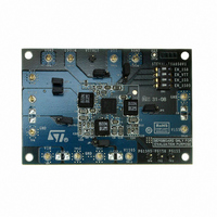
KIT EVAL PM6641 CHIPSET/DDR2/3
Manufacturer
STMicroelectronics
Type
DC/DC Switching Converters, Regulators & Controllersr
Specifications of STEVAL-ISA050V1
Main Purpose
Special Purpose DC/DC, DDR Memory Supply
Outputs And Type
4, Non-Isolated
Power - Output
14.7W
Voltage - Output
1.05V, 1.5V, 1.8V, 0.9V
Current - Output
4A, 2.8A, 2.5A, 2A
Voltage - Input
2.7 ~ 5.5V
Regulator Topology
Buck
Frequency - Switching
750kHz
Board Type
Fully Populated
Utilized Ic / Part
PM6641
Input Voltage
2.7 V to 5.5 V
Product
Power Management Modules
Silicon Manufacturer
ST Micro
Silicon Core Number
PM6641
Kit Application Type
Power Management - Voltage Regulator
Application Sub Type
Monolithic Voltage Regulator
Kit Contents
Board
Lead Free Status / RoHS Status
Lead free / RoHS Compliant
For Use With/related Products
PM6641
Other names
497-8425
Available stocks
Company
Part Number
Manufacturer
Quantity
Price
Company:

Part Number:
STEVAL-ISA050V1
Manufacturer:
STMicroelectronics
Quantity:
1


Components selection
8.5
40/47
Layout guidelines
Each signal is referred to AGND, the analog ground. In a typical 4-layers PCB one internal
layer should be dedicated to this common ground. The IC thermal pad must be connected to
AGND plane through multiple VIAs, in order to remove the IC heat and to obtain the best
performance. Furthermore, each switching regulator has a dedicated power ground
(SGND_1Sxx); all these SGNDs must be star-connected, in a single point, with AGND.
For each switching section the power components (inductor and input/output capacitors)
must be placed near the VSW_1Sxx, VIN_1Sxx and SGND_1Sxx pins and connected with
large (at least 20 mils or larger) and short PCB traces, in order to limit the path of the current
high frequency components and, consequently, to reduce the injected noise. If the power
components routing involves more than one layer, as many VIAs as possible must be
inserted to reduce the series resistance and improve the global efficiency.
The VTT external components (input and output capacitors) must be placed near the LDO
regulator input (LDOIN) and output (VTT) pins, and must be routed with large and short
traces, in order to limit the parasitic series resistance.
The feedback pins (VFB_1Sxx and VTTFB) must reach the feedback points through
dedicated PCB traces, typically 10 mils width; larger feedback traces are not required.
For reference layout, refer to PM6641 demonstration kit document.
Doc ID 13510 Rev 3
PM6641
Related parts for STEVAL-ISA050V1
Image
Part Number
Description
Manufacturer
Datasheet
Request
R

Part Number:
Description:
BOARD RGB CTR ST7,STP08C596MTR
Manufacturer:
STMicroelectronics
Datasheet:

Part Number:
Description:
Power Management IC Development Tools Full Speed USB to RS232 Bridge Demo
Manufacturer:
STMicroelectronics
Datasheet:
Part Number:
Description:
Power Management IC Development Tools 2.5W solar eval BRD USB SPV1040 LD39050
Manufacturer:
STMicroelectronics
Datasheet:

Part Number:
Description:
BOARD EVAL FOR MEMS SENSORS
Manufacturer:
STMicroelectronics
Datasheet:

Part Number:
Description:
KIT DEV STARTER ST10F276Z5
Manufacturer:
STMicroelectronics
Datasheet:

Part Number:
Description:
BOARD EVAL HDMI $ VIDEO SWITCH
Manufacturer:
STMicroelectronics
Datasheet:

Part Number:
Description:
BOARD DEMO ACCELEROMETER DIL24
Manufacturer:
STMicroelectronics
Datasheet:

Part Number:
Description:
BOARD STLM75/STDS75/ST72F651
Manufacturer:
STMicroelectronics
Datasheet:

Part Number:
Description:
EVAL BOARD 3AXIS MEMS ACCELLRMTR
Manufacturer:
STMicroelectronics
Datasheet:

Part Number:
Description:
BOARD EVAL 8BIT MICRO + TDE1708
Manufacturer:
STMicroelectronics
Datasheet:
Part Number:
Description:
STMicroelectronics [RIPPLE-CARRY BINARY COUNTER/DIVIDERS]
Manufacturer:
STMicroelectronics
Datasheet:
Part Number:
Description:
STMicroelectronics [LIQUID-CRYSTAL DISPLAY DRIVERS]
Manufacturer:
STMicroelectronics
Datasheet:
Part Number:
Description:
BOARD EVAL FOR MEMS SENSORS
Manufacturer:
STMicroelectronics
Datasheet: