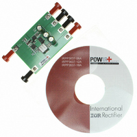
IRPP3637-12A International Rectifier, IRPP3637-12A Datasheet

IRPP3637-12A
Specifications of IRPP3637-12A
Related parts for IRPP3637-12A
IRPP3637-12A Summary of contents
Page 1
ACCURATE SYNCHRONOUS PWM CONTROLLER FEATURES 0.8V Reference Voltage Operates with a single 5V Supply Voltage Internal 400kHz Oscillator Soft-Start Function Fixed Frequency Voltage Mode Short Circuit Protection APPLICATIONS Computer Peripheral Voltage Regulator Memory Power supplies Graphics Card Low cost ...
Page 2
IR3637SPBF ABSOLUTE MAXIMUM RATINGS Vcc Supply Voltage ................................................ Vc Supply Voltage .................................................. Storage Temperature Range ..................................... Operating Junction Temperature Range ..................... ESD Classification ................................................. Moisture Sensitivity Level ........................................ Caution: Stresses above those listed in “Absolute Maximum Rating” may cause permanent ...
Page 3
PARAMETER SYM Error Amp Fb Voltage Input Bias Current I Fb Voltage Input Bias Current I Transconductance g Oscillator Frequency Freq Ramp-Amplitude Voltage V Output Drivers Rise Time, Hdrv, Ldrv Fall Time,Hdrv, Ldrv Dead Band Time T Max Duty Cycle ...
Page 4
IR3637SPBF BLOCK DIAGRAM 3V 25uA SS/SD 64uA Max 8 POR 0.8V 25K Error Amp 25K Fb 1 Comp 7 Figure 2 - Simplified block diagram of the IR3637. THEORY OF OPERATION Introduction The IR3637 is a fixed frequency, voltage mode ...
Page 5
THEORY OF OPERATION Soft-Start The IR3637 has a programmable soft-start to control the output voltage rise and limit the current surge at the start- up. To ensure correct start-up, the soft-start sequence initiates when the Vc and Vcc rise above ...
Page 6
IR3637SPBF APPLICATION INFORMATION Design Example: The following example is a typical application for IR3637. Appliaction circuit is shown in page 12 Vcc = 5V IN Vc=12V V = 1.8V OUT OUT ∆V = 50mV OUT ...
Page 7
D×(1-D) ---(3) RMS OUT Where the Duty Cycle, D=V /V OUT IN the RMS value of the input capacitor current. RMS I is the output current for each channel. OUT For I =6A ...
Page 8
IR3637SPBF For this design, IRF8910 is a good choice. The device provides two N-MOSFETs in a compact SOIC 8-Pin pack- age. The IRF8910 has the following data 20V DSS I = 10A D R =18.3Ω =4.5V ...
Page 9
Note that this method requires that the output capacitor should have enough ESR to satisfy stability requirements. In general the output capacitor’s ESR generates a zero typically at 5kHz to 50kHz which is essential for an ac- ceptable phase margin. ...
Page 10
IR3637SPBF For a general solution for unconditionally stability for any type of output capacitors wide range of ESR values we should implement local feedback with a compensa- tion network. The typically used compensation network for voltage-mode controller is ...
Page 11
Place second pole at the ESR zero ESR 2π × C × Check if R > too small, increase R and ...
Page 12
IR3637SPBF TYPICAL APPLICATION Two Supplies Application: Vc=12V, Vin=Vcc= Gnd 12V Vcc C3 1uF SS/SD U1 IR3637 C6 0.1uF Comp C9 Gnd 1.8nF C11 R4 47pF 16K 150uF 150uF C4 C5 ...
Page 13
TYPICAL APPLICATION Single 5V Application C3 C4 Vcc Vc HDrv U1 SS/SD C8 IR3637 LDrv Comp C9 Fb Gnd R4 Figure 12 - Typical application for single 5V Rev. 1.1 06/16/ www.irf.com ...
Page 14
IR3637SPBF TYPICAL APPLICATION Two Supplies Application, Vcc=Vc=12V, Vin=5V 12V C3 Vcc Vc HDrv U1 SS/SD C8 IR3637 LDrv Comp C9 Gnd R4 Figure 13 - Typical application using 12V for biasing both Vcc and Vc and 5V for Bus Voltage ...
Page 15
TYPICAL OPERATING CHARACTERISTICS Vfb vs. Temperature 800.50 800.00 799.50 799.00 798.50 798.00 797. E/A's Transconductance 0.62 0.6 0.58 0.56 0.54 0.52 0 Temp, C Static Vc Current 4.25 4 3.75 3.5 ...
Page 16
IR3637SPBF TYPICAL OPERATING CHARACTERISTICS Dynamic Vc Current 12.75 12.5 12.25 12 11.75 11 Temp, C Fall Time-HDrv Temp ...
Page 17
TYPICAL PERFORMANCE CURVES Test Conditions: Vcc=Vin=5V, Vc=12V, Vout=1.8V, Iout=0-7A, Ta=Room Temp, No Air Flow. Unless otherwise specified. Figure 14 - Start up waveforms Ch1: Vin=Vcc, Ch2: Vc, Ch3: Vss, Ch4: Vout Figure 16 - Gates waveforms Ch1: Hdrv, Ch2: Ldrv, ...
Page 18
IR3637SPBF TYPICAL OPERATING WAVEFORMS Test Conditions: Vcc=Vin=5V, Vc=12V, Vout=1.8V, Iout=0-7A, Ta=Room Temp, No Air Flow. Unless otherwise specified. Figure 18 - Shutdown by shorting the SS pin Ch1: Hdrv, Ch2: Ldrv, Ch3:SS ILoad=5A Figure 20 - Load Transient (0-5A) Ch1: ...
Page 19
TYPICAL PERFORMANCE CURVES Test Conditions: Vcc=Vin=5V, Vc=12V, Vout=1.8V, Iout=0-8A, Ta=Room Temp, No Air Flow. Unless otherwise specified. V c=12V , V cc t=0-8A, F s=40 0kHz ...
Page 20
IR3637SPBF 8-Pin Surface Mount, Narrow Body PIN NO NOTE: ALL MEASUREMENTS ARE IN MILLIMETERS. 20 (S) SOIC Package DETAIL-A 0.38 ± 0.015 8-PIN SYMBOL MIN MAX A 4.80 ...
Page 21
PACKAGE SHIPMENT METHOD PKG PACKAGE DESIG DESCRIPTION S SOIC, NARROW BODY This product has been designed and qualified for the Consumer market. IR WORLD HEADQUARTERS: 233 Kansas St., El Segundo, California 90245, USA Tel: (310) 252-7105 Rev. 1.1 06/16/05 PIN ...


