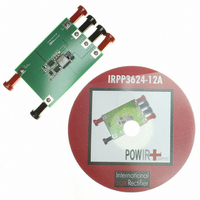
IRPP3624-12A International Rectifier, IRPP3624-12A Datasheet

IRPP3624-12A
Specifications of IRPP3624-12A
Related parts for IRPP3624-12A
IRPP3624-12A Summary of contents
Page 1
HIGH FREQUENCY SYNCHRONOUS PWM BUCK CONTROLLER Features • Internal 600kHz Oscillator • Operates with Single 5V or 12V Supply • Programmable Over Current Protection • Hiccup Current Limit Using MOSFET R sensing • Precision Reference Voltage (0.6V) • Programmable Soft-Start ...
Page 2
ABSOLUTE MAXIMUM RATINGS (Voltages referenced to GND) • Vcc Supply Voltage ................................................… -0.5V to 16V • Vc Supply Voltage …………………………………….. -0.5V to 30V • Storage Temperature Range ..................................... -65°C To 150°C • Operating Junction Temperature Range ................... -40°C To 150°C ...
Page 3
Block Diagram Vcc 3V 3V 20uA 40uA 3uA OCP POR 0.6V Error Amp Fb Comp Gnd Fig. 2: Simplified block diagram of the IR3624 3V Bias Generator 0.6V Thermal Shutdown UVLO POR Vc PWM Comp R Q ...
Page 4
Pin Description Pin Name 1 Vcc This pin provides power for the internal blocks of the IC as well as powers the low side driver. A minimum of 0.1uF, high frequency capacitor must be connected from this pin to power ...
Page 5
Recommended Operating Conditions Symbol Definition V Supply Voltage cc V Supply Voltage c F Operating Frequency s T Junction Temperature j Electrical Specifications Unless otherwise specified, these specification apply over V Parameter SYM Reference Voltage Feedback Voltage V Accuracy Supply ...
Page 6
Parameter SYM Error Amplifier Input Bias Current I FB Source/Sink Current I(source/Sink) Transconductance gm Soft Start/SD Soft Start Current I SS Shutdown Output SD Threshold Over Current Protection OCSET Current I OCSET Hiccup Current I Hiccup Hiccup Duty Cycle Hiccup(duty) ...
Page 7
TYPICAL OPERATING CHARACTERISTICS Vfb (mV) 603 602 601 600 599 598 597 596 595 -40 -30 -20 - 100 110 120 Tem p ['C] Iccq(mA) 8 7.5 7 6.5 6 ...
Page 8
Circuit Description THEORY OF OPEARTION Introduction The IR3624 is a voltage synchronous controller and operates with a fixed 600kHz switching frequency, allowing the use of small external components. The output voltage is set by feedback pin (Fb) and the internal ...
Page 9
Soft-Start The IR3624 has programmable soft-start to control the output voltage rise and limit the inrush current during start-up. To ensure correct start-up, sequence initiates when Vcc and Vc rise above their threshold and generate the Power On Ready (POR) ...
Page 10
Over-Current Protection The over current protection is performed by sensing current through the R DS(on) MOSFET. This method enhances the converter’s efficiency and reduce cost by eliminating a current sense resistor. As shown in figure 7, an external resistor (R ...
Page 11
Application Information Design Example: The following example is a typical application for IR3624. The application circuit is shown in page17 max ...
Page 12
Input Capacitor Selection The input filter capacitor should be selected based on how much ripple the supply can tolerate on the DC input line. The ripple current generated during the on time of upper MOSFET should be provided by input ...
Page 13
Power MOSFET Selection The IR3624 uses two N-Channel MOSFETs. The selections criteria to meet power transfer requirements is based on maximum drain-source voltage (V ), gate-source drive voltage (V DSS maximum output current, On-resistance R and thermal management. The MOSFET ...
Page 14
Feedback Compensation The IR3624 is a voltage mode controller; the control loop is a single voltage feedback path including error amplifier and error comparator. To achieve fast transient response and accurate output regulation, a compensation circuit is necessary. The goal ...
Page 15
To cancel one of the LC filter poles, place the zero before the LC filter resonant frequency pole π ...
Page 16
Based on the frequency of the zero generated by output capacitor and its ESR versus crossover frequency, the compensation type can be different. The table below compensation types and location of crossover frequency. Compensator F vs. F ESR o type ...
Page 17
Programming the Current-Limit The Current-Limit threshold can be set by connecting a resistor (R ) from drain of low SET side MOSFET to the OCSet pin. The resistor can be calculated by using equation (3). The R has a positive ...
Page 18
Vcc 0.1uF C1 IR3624 0.1uF Gnd Comp Fig.16: Application circuit for 13.2V to 1.8V Using ceramic output capacitor with typeIII compensation D1 BAT54 10uF 0.1uF ceramic HDrv R7 OCSet 9K Q1 LDrv ...
Page 19
TYPICAL OPERATING WAVEFORMS Vin=13.2V, Vo=1.8V, Io=0-6A, Fs=600 kHz, Room Temperature, No Air Flow Fig.17: Start Load Fig.19: Output Voltage Ripple at 6A load ...
Page 20
TYPICAL OPERATING WAVEFORMS Vin=13.2V, Vo=1.8V, Io=0-6A, Fs=600 kHz, Room Temperature, No Air Flow Fig.23: Bode Plot at 10%of load shows a bandwidth of 70kHz and phase margin of 62 degree ...
Page 21
MLPD Package D E SEATING PLANE Terminal 1 Leads on 2 sides Identifier (ND- TAPE & REEL ORIENTATION IR WORLD HEADQUARTERS: This product has been designed and qualified ...


