NCP1422EVB ON Semiconductor, NCP1422EVB Datasheet - Page 5
NCP1422EVB
Manufacturer Part Number
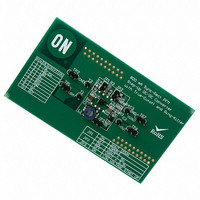
NCP1422EVB
Description
EVAL BOARD FOR NCP1422
Manufacturer
ON Semiconductor
Specifications of NCP1422EVB
Design Resources
NCP1422 EVB BOM NCP1422EVB Gerber Files NCP1422EVB Schematic
Main Purpose
DC/DC, Step Up
Outputs And Type
1, Non-Isolated
Voltage - Output
3.3 ~ 5 V
Current - Output
800mA
Voltage - Input
2.5V, 3.6V
Regulator Topology
Boost
Frequency - Switching
1.2MHz
Board Type
Fully Populated
Utilized Ic / Part
NCP1422
Lead Free Status / RoHS Status
Lead free / RoHS Compliant
Power - Output
-
Lead Free Status / Rohs Status
Lead free / RoHS Compliant
For Use With/related Products
NCP1422
Other names
NCP1422EVBOS


1.220
1.210
1.200
1.190
1.180
1.205
1.200
1.195
1.190
1.185
1.180
1.0
0.9
0.8
0.7
0.6
0.5
Figure 6. L
−40
−40
Figure 4. Reference Voltage vs. Temperature
1
Figure 2. Reference Voltage vs. Output Current
V
L = 10 mH
C
C
C
T
A
OUT
IN
OUT
REF
= 25_C
−20
−20
= 22 mF
= 3.3 V
= 1.0 mF
= 22 mF
X
Switch Max. ON Time vs. Temperature
AMBIENT TEMPERATURE, T
AMBIENT TEMPERATURE, T
OUTPUT CURRENT, I
0
0
10
20
20
TYPICAL OPERATING CHARACTERISTICS
40
40
V
IN
LOAD
= 2.0 V
100
V
C
I
60
60
V
/mA
REF
OUT
REF
A
A
IN
/°C
/°C
= 1.5 V
= 0 mA
V
= 200 nF
= 3.3 V
IN
80
80
= 2.5 V
http://onsemi.com
NCP1422
1000
100
100
5
1.180
1.220
1.210
1.200
1.190
0.6
0.5
0.4
0.3
0.2
0.1
0.0
1.6
1.4
1.1
0.9
0.6
Figure 3. Reference Voltage vs. Voltage at OUT Pin
1.5
−40
0
Figure 5. Switch ON Resistance vs. Temperature
Figure 7. Minimum Startup Battery Voltage vs.
C
I
T
REF
A
REF
V
= 25°C
OUT
−20
2
= 0 mA
OUTPUT LOADING CURRENT, I
= 200 nF
50
= 3.3 V
AMBIENT TEMPERATURE, T
VOLTAGE AT OUT PIN, V
2.5
0
Loading Current
100
20
3
P−FET (M2)
3.5
40
150
N−FET (M1)
OUT
60
4
LOAD
A
/V
/°C
200
T
/mA
A
4.5
80
= 25°C
100
250
5
Related parts for NCP1422EVB
Image
Part Number
Description
Manufacturer
Datasheet
Request
R

Part Number:
Description:
Sync-Rect PFM Step-Up DC-DC Converter
Manufacturer:
ON Semiconductor
Datasheet:
Part Number:
Description:
ON Semiconductor [VOLTAGE REGULATOR]
Manufacturer:
ON Semiconductor
Datasheet:
Part Number:
Description:
357-036-542-201 CARDEDGE 36POS DL .156 BLK LOPRO
Manufacturer:
ON Semiconductor
Datasheet:
Part Number:
Description:
357-036-542-201 CARDEDGE 36POS DL .156 BLK LOPRO
Manufacturer:
ON Semiconductor
Datasheet:
Part Number:
Description:
357-036-542-201 CARDEDGE 36POS DL .156 BLK LOPRO
Manufacturer:
ON Semiconductor
Datasheet:
Part Number:
Description:
357-036-542-201 CARDEDGE 36POS DL .156 BLK LOPRO
Manufacturer:
ON Semiconductor
Datasheet:
Part Number:
Description:
357-036-542-201 CARDEDGE 36POS DL .156 BLK LOPRO
Manufacturer:
ON Semiconductor
Datasheet:
Part Number:
Description:
357-036-542-201 CARDEDGE 36POS DL .156 BLK LOPRO
Manufacturer:
ON Semiconductor
Datasheet:
Part Number:
Description:
357-036-542-201 CARDEDGE 36POS DL .156 BLK LOPRO
Manufacturer:
ON Semiconductor
Datasheet:
Part Number:
Description:
357-036-542-201 CARDEDGE 36POS DL .156 BLK LOPRO
Manufacturer:
ON Semiconductor
Datasheet:
Part Number:
Description:
357-036-542-201 CARDEDGE 36POS DL .156 BLK LOPRO
Manufacturer:
ON Semiconductor
Datasheet:
Part Number:
Description:
357-036-542-201 CARDEDGE 36POS DL .156 BLK LOPRO
Manufacturer:
ON Semiconductor
Datasheet:
Part Number:
Description:
Manufacturer:
ON Semiconductor
Datasheet:
Part Number:
Description:
Manufacturer:
ON Semiconductor
Datasheet: