DC1319B-A Linear Technology, DC1319B-A Datasheet - Page 13
DC1319B-A
Manufacturer Part Number
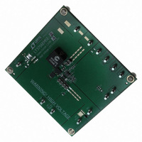
DC1319B-A
Description
BOARD EVAL LED DRIVER LT3756
Manufacturer
Linear Technology
Specifications of DC1319B-A
Current - Output / Channel
500mA
Outputs And Type
1, Non-Isolated
Voltage - Output
100V
Features
Dimmable
Voltage - Input
8 ~ 80V
Utilized Ic / Part
LT3756
Lead Free Status / RoHS Status
Lead free / RoHS Compliant
Other names
DC1319A-A
DC1319A-A
DC1319A-A


method uses the PWM pin to modulate the current source
between zero and full current to achieve a precisely pro-
grammed average current. To make PWM dimming more
accurate, the switch demand current is stored on the VC
node during the quiescent phase when PWM is low. This
feature minimizes recovery time when the PWM signal goes
high. To further improve the recovery time, a disconnect
switch may be used in the LED current path to prevent the
ISP node from discharging during the PWM signal low
phase. The minimum PWM on or off time will depend on
the choice of operating frequency and external component
selection. With operation in discontinuous conduction
mode (DCM), regulated current pulses as short as 1µs are
achievable. But, the best overall combination of PWM and
analog dimming (with CTRL) is available if the minimum
PWM pulse is at least six switching cycles.
Programming the Switching Frequency
The RT frequency adjust pin allows the user to program
the switching frequency from 100kHz to 1MHz to optimize
efficiency/performance or external component size. Higher
frequency operation yields smaller component size but
increases switching losses and gate driving current, and
may not allow sufficiently high or low duty cycle operation.
Lower frequency operation gives better performance at the
cost of larger external component size. For an appropriate
R
RT pin to GND is required—do not leave this pin open.
Table 1. Switching Frequency vs R
applicaTions inForMaTion
T
resistor value see Table 1. An external resistor from the
f
OSC
1000
900
800
700
600
500
400
300
200
100
(kHz)
T
Value
R
T
10.0
11.8
13.0
15.4
17.8
21.0
26.7
35.7
53.6
100
(kΩ)
Thermal Considerations
The LT3756 series is rated to a maximum input voltage
of 100V. Careful attention must be paid to the internal
power dissipation of the IC at higher input voltages to
ensure that a junction temperature of 125°C (150°C for
H-grade) is not exceeded. This junction limit is especially
Duty Cycle Considerations
Switching duty cycle is a key variable defining converter
operation, therefore, its limits must be considered when
programming the switching frequency for a particular
application. The fixed minimum on-time and minimum
off-time (see Figure 4) and the switching frequency define
the minimum and maximum duty cycle of the switch,
respectively. The following equations express the mini-
mum/maximum duty cycle:
Min Duty Cycle = (minimum on-time) • switching fre-
quency
Max Duty Cycle = 1 – (minimum off-time) • switching
frequency
When calculating the operating limits, the typical values
for on/off-time in the data sheet should be increased by
at least 60ns to allow margin for PWM control latitude,
GATE rise/fall times and SW node rise/fall times.
LT3756/LT3756-1/LT3756-2
300
250
200
150
100
50
Figure 4. Typical Minimum On and Off
Pulse Width vs Temperature
0
–50
C
GATE
–25
= 3300pF
MINIMUM ON-TIME
MINIMUM OFF-TIME
0
TEMPERATURE (°C)
25
50
75
100
125
375612 F04
150
375612fb
Related parts for DC1319B-A
Image
Part Number
Description
Manufacturer
Datasheet
Request
R

Part Number:
Description:
CD ROM LINEARVIEW DATASHEETS
Manufacturer:
Linear Technology

Part Number:
Description:
Standalone Linear Li-Ion Battery Charger with Thermal Regulation in ThinSOT
Manufacturer:
Linear Technology Corporation
Datasheet:
Part Number:
Description:
Low noise, high frequency, 8th order linear phase lowpass filter
Manufacturer:
Linear Technology Corporation
Datasheet:
Part Number:
Description:
Manufacturer:
Linear Technology Corporation
Datasheet:
Part Number:
Description:
Manufacturer:
Linear Technology Corporation
Datasheet:
Part Number:
Description:
Manufacturer:
Linear Technology Corporation
Datasheet:
Part Number:
Description:
Manufacturer:
Linear Technology Corporation
Datasheet:
Part Number:
Description:
Manufacturer:
Linear Technology Corporation
Datasheet:
Part Number:
Description:
Manufacturer:
Linear Technology Corporation
Datasheet:
Part Number:
Description:
Manufacturer:
Linear Technology Corporation
Datasheet:
Part Number:
Description:
Dual and Quad, JFET Input Precision High Speed Op Amps
Manufacturer:
Linear Technology Corporation
Datasheet:
Part Number:
Description:
Manufacturer:
Linear Technology Corporation
Datasheet:
Part Number:
Description:
1, 2, 6 and 8 Channel, 10-Bit Serial I/O Data Acquisition Systems
Manufacturer:
Linear Technology Corporation
Datasheet:
Part Number:
Description:
Manufacturer:
Linear Technology Corporation
Datasheet:
Part Number:
Description:
Universal dual filter building block
Manufacturer:
Linear Technology Corporation
Datasheet: