TC1016/17EV Microchip Technology, TC1016/17EV Datasheet - Page 10
TC1016/17EV
Manufacturer Part Number
TC1016/17EV
Description
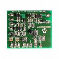
BOARD DEMO FOR TC1016/TC1017
Manufacturer
Microchip Technology
Specifications of TC1016/17EV
Design Resources
TC1016/17EV Gerber Files
Channels Per Ic
1 - Single
Voltage - Output
1.8V, 3V
Current - Output
150mA, 150mA
Voltage - Input
2.7 ~ 6V
Regulator Type
Positive Fixed
Operating Temperature
-40°C ~ 125°C
Board Type
Fully Populated
Utilized Ic / Part
TC1016, TC1017
Processor To Be Evaluated
TC1016 and TC1017
Lead Free Status / RoHS Status
Contains lead / RoHS non-compliant
Lead Free Status / RoHS Status
Lead free / RoHS Compliant, Contains lead / RoHS non-compliant


TC1017
4.0
The TC1017 is a precision, fixed-output, linear voltage
regulator. The internal linear pass element is a
P-channel MOSFET. As with all P-channel CMOS
LDOs, there is a body drain diode with the cathode
connected to V
(Figure 4-1).
As is shown in Figure 4-1, the output voltage of the
LDO is sensed and divided down internally to reduce
external component count. The internal error amplifier
has a fixed bandgap reference on the inverting input
and the sensed output voltage on the non-inverting
input. The error amplifier output will pull the gate
voltage down until the inputs of the error amplifier are
equal to regulate the output voltage.
Output overload protection is implemented by sensing
the current in the P-channel MOSFET. During a shorted
or faulted load condition in which the output voltage
falls to less than 0.5V, the output current is limited to a
typical value of 120 mA. The current-limit protection
helps prevent excessive current from damaging the
Printed Circuit Board (PCB).
An internal thermal sensing device is used to monitor
the junction temperature of the LDO. When the sensed
temperature is over the set threshold of 160°C (typical),
the P-channel MOSFET is turned off. When the P-chan-
nel is off, the power dissipation internal to the device is
almost zero. The device cools until the junction temper-
FIGURE 4-1:
FIGURE 4-2:
DS21813D-page 10
DETAILED DESCRIPTION
IN
and the anode connected to V
TC1017 Block Diagram (5-Pin SC-70 Pinout).
Typical Application Circuit (5-Pin SC-70 Pinout).
R
SOURCE
1
2
3
SHDN
NC
GND
SHDN
Control
Temp.
Over
V
IN
1
2
3
OUT
V
REF
SHDN
NC
GND
TC1017
Current Limit
Feedback Resistors
R
1
V
ature is approximately 150°C and the P-channel is
turned on. If the internal power dissipation is still high
enough for the junction to rise to 160°C, it will again shut
off and cool. The maximum operating junction tempera-
ture of the device is 125°C. Steady-state operation at or
near the 160°C overtemperature point can lead to per-
manent damage of the device.
The output voltage V
input operating voltage range (2.7V to 6.0V) and the
entire load range (0 mA to 150 mA). The output voltage
is sensed through an internal resistor divider and
compared with a precision internal voltage reference.
Several
changing the value of the internal resistor divider.
Figure 4-2 shows a typical application circuit. The
regulator is enabled any time the shutdown input pin is
at or above V
shutdown input pin is below V
the SHDN feature is not used, tie the SHDN pin directly
to the input supply voltage source. While in shutdown,
the supply current decreases to 0.006 µA (typical) and
the P-channel MOSFET is turned off.
As shown in Figure 4-2, batteries have internal source
impedance. An input capacitor is used to lower the
input impedance of the LDO. In some applications, high
input impedance can cause the LDO to become
unstable.
compensate for this.
Error
Amp
+
-
R
EA
OUT
V
2
IN
5
4
C
fixed-output
C
OUT
Adding
IN
Body
Diode
IH
. It is shut down (disabled) any time the
1 µF Ceramic
1 µF Ceramic
V
OUT
V
IN
OUT
more
5
4
© 2005 Microchip Technology Inc.
Load
voltages are available
remains stable over the entire
input
IL
. For applications where
capacitance
can
by
Related parts for TC1016/17EV
Image
Part Number
Description
Manufacturer
Datasheet
Request
R


Part Number:
Description:
IC REG LDO 3.0V 80MA SD SC-70-5
Manufacturer:
Microchip Technology
Datasheet:
Part Number:
Description:
IC REG LDO 3.3V 80MA SD SC70-5
Manufacturer:
Microchip Technology
Datasheet:

Part Number:
Description:
IC REG LDO 2.7V SOT-23-5
Manufacturer:
Microchip Technology
Datasheet:
Part Number:
Description:
IC REG LDO 1.8V 80MA SD SC-70-5
Manufacturer:
Microchip Technology
Datasheet:
Part Number:
Description:
IC REG LDO 1.85V SOT-23-5
Manufacturer:
Microchip Technology
Datasheet:
Part Number:
Description:
IC REG LDO 2.8V SOT-23-5
Manufacturer:
Microchip Technology
Datasheet:
Part Number:
Description:
IC REG LDO 4.0V SOT-23-5
Manufacturer:
Microchip Technology
Datasheet:
Part Number:
Description:
IC REG LDO 4.0V SC70-5
Manufacturer:
Microchip Technology
Datasheet:
Part Number:
Description:
IC CMOS LDO 80MA 3.3V SOT23-5
Manufacturer:
Microchip Technology
Datasheet:
Part Number:
Description:
IC CMOS LDO 80MA 1.8V SOT23-5
Manufacturer:
Microchip Technology
Datasheet:
Part Number:
Description:
IC REG LDO 2.8V 80MA SD SC-70-5
Manufacturer:
Microchip Technology
Datasheet:
Part Number:
Description:
IC REG LDO 2.7V 80MA SD SC-70-5
Manufacturer:
Microchip Technology
Datasheet:

Part Number:
Description:
80mA Tiny CMOS LDO With Shutdown 5 SOT-23 T/R
Manufacturer:
Microchip Technology
Datasheet: