DM300019 Microchip Technology, DM300019 Datasheet - Page 29
DM300019
Manufacturer Part Number
DM300019
Description
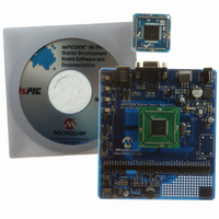
BOARD DEMO DSPICDEM 80L STARTER
Manufacturer
Microchip Technology
Type
MCUr
Specifications of DM300019
Contents
Board, CD, Sample Part
Processor To Be Evaluated
dsPIC30F and dsPIC33F
Interface Type
RS-232
Silicon Manufacturer
Microchip
Silicon Core Number
DsPIC30F6014A, DsPIC33FJ256GP710
Silicon Family Name
DsPIC30F And DsPIC33F
Kit Contents
Development Board And Docs On CD
Rohs Compliant
Yes
Lead Free Status / RoHS Status
Lead free / RoHS Compliant
For Use With/related Products
dsPIC30F, dsPIC33F
Lead Free Status / Rohs Status
Lead free / RoHS Compliant
Available stocks
Company
Part Number
Manufacturer
Quantity
Price
Company:

Part Number:
DM300019
Manufacturer:
Microchip Technology
Quantity:
135
Company:
Part Number:
DM300019
Manufacturer:
MICROCHIP
Quantity:
12 000


3.1
3.2
3.3
© 2006 Microchip Technology Inc.
INTRODUCTION
HIGHLIGHTS
DEMONSTRATION PROGRAM SUMMARY
Chapter 3. Demonstration Program Operation
The dsPICDEM 80-Pin Starter Development Board is shipped with example
applications programmed into the dsPIC DSC device. These examples exercise
several of the dsPIC DSC peripherals such as the 12-bit Analog-to-Digital Converter
(ADC) and UART interfaces. This chapter provides an overview of the demonstration
code. Detailed information on the dsPICDEM 80-Pin Starter Development Board
hardware is presented in Chapter 4. “dsPICDEM™ Development Board Hardware”
and Appendix A. “Drawings and Schematics”.
Items discussed in this chapter are:
• Demonstration Program Summary
• Demonstration Code Operation
• Board Self-test
The preprogrammed demonstration program includes two functionally separate code
modules:
• Demonstration code module
• Board self-test code module
These two code modules have been combined into one composite program and coded
into the device. The board self-test code module has been included on the CD as a
library archive only and is briefly discussed at the end of this section. The following
sections present the operation of each module.
When power is applied to the dsPICDEM 80-Pin Starter Development Board, the dsPIC
DSC device begins executing the demonstration program, which consists of three
distinct functional tasks:
• Interrupt processing
• Analog-to-digital conversion
• Digital-to-analog conversion
3.3.1
To illustrate interrupt processing, the demonstration program uses switches S1 and S2
as signals to drive LEDs RD4 and RD5 (output devices). When switch S1 is pressed
(to represent an interrupt), LED RD4 blinks at a 1 Hz rate (once per second) until switch
S1 is pressed again. Similarly, when switch S2 is pressed, LED RD5 blinks until switch
S2 is pressed again. Timer 1 is set up to interrupt every half second.
Interrupt Processing
DEVELOPMENT BOARD USER’S GUIDE
dsPICDEM™ 80-PIN STARTER
DS51584B-page 25
Related parts for DM300019
Image
Part Number
Description
Manufacturer
Datasheet
Request
R

Part Number:
Description:
Manufacturer:
Microchip Technology Inc.
Datasheet:
Part Number:
Description:
Manufacturer:
Microchip Technology Inc.
Datasheet:
Part Number:
Description:
Manufacturer:
Microchip Technology Inc.
Datasheet:
Part Number:
Description:
Manufacturer:
Microchip Technology Inc.
Datasheet:
Part Number:
Description:
Manufacturer:
Microchip Technology Inc.
Datasheet:
Part Number:
Description:
Manufacturer:
Microchip Technology Inc.
Datasheet:
Part Number:
Description:
Manufacturer:
Microchip Technology Inc.
Datasheet:
Part Number:
Description:
Manufacturer:
Microchip Technology Inc.
Datasheet: