ATSTK600 Atmel, ATSTK600 Datasheet - Page 42
ATSTK600
Manufacturer Part Number
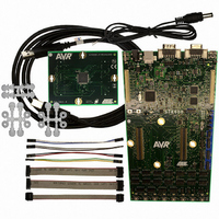
ATSTK600
Description
DEV KIT FOR AVR/AVR32
Manufacturer
Atmel
Series
AVR®r
Type
MCUr
Specifications of ATSTK600
Processor To Be Evaluated
AVR and AVR32
Data Bus Width
8 bit
Interface Type
RS-232, USB
Silicon Manufacturer
Atmel
Core Architecture
AVR
Core Sub-architecture
AVR UC3
Silicon Core Number
STK600
Silicon Family Name
AVR
Kit Contents
Board
Rohs Compliant
Yes
For Use With/related Products
Atmel AVR Devices
For Use With
ATSTK600-ATTINY10 - STK600-ATTINY10 SOCKET PACKAGE
Lead Free Status / RoHS Status
Lead free / RoHS Compliant
Contents
-
Lead Free Status / Rohs Status
Lead free / RoHS Compliant
Available stocks
Company
Part Number
Manufacturer
Quantity
Price
Company:

Part Number:
ATSTK600
Manufacturer:
Atmel
Quantity:
135
Company:
Part Number:
ATSTK600-ATTINY10
Manufacturer:
Atmel
Quantity:
135
Company:
Part Number:
ATSTK600-DIP40
Manufacturer:
Atmel
Quantity:
135
Company:
Part Number:
ATSTK600-RC14
Manufacturer:
Atmel
Quantity:
135
Company:
Part Number:
ATSTK600-RC15
Manufacturer:
Atmel
Quantity:
135


11.8 PARAM_DISCHARGEDELAY
11.9 PARAM2_AREF0
11.10 PARAM2_AREF1
11.11 PARAM2_CLOCK_CONF
Table 11-3. Two-byte value.
Table 11-4. Two-byte value.
D15
OCT3
D7
DAC5
42
AVR079
D14
OCT2
D6
DAC4
D13
OCT1
D5
DAC3
This parameter is intended to be used as a way of telling if the power on STK600 has
been lost or turned off and then back again.
This way, the host software can tell if the programmer needs to be initialized again
before continuing with its operation.
If the returned value is 0 the CMD_SET_CONTROL_STACK must be executed
before continuing with any high voltage programming commands.
This parameter sets a time period for which the reset line has a higher resistance for
each time it is toggled.
The purpose is to reduce the maximum current caused by the discharge/recharge of
a decoupling capacitor connected to the reset pin.
When the reset is toggled a resistor of 510ohm will be switched in, which reduces the
peak current to an acceptable level for the internal components of the STK600.
The delay should be set to: t>510ohm*C
If no capacitor is connected this parameter could be set to 0.
The parameter value is voltage in volts x100, i.e. a parameter value of 449 (decimal)
corresponds to 4.49V.
The maximum value is 5.5V, or parameter value 550.
Same as for AREF0.
This is a two-byte value, which configures the chip oscillator.
The frequency is given by the formula:
Equation 11-1. Frequency
f
=
2
OCT
⋅
D12
OCT0
D4
DAC2
2
−
2078
DAC
1024
D11
DAC9
D3
DAC1
DAC8
DAC0
D10
D2
D9
DAC7
D1
X
DAC6
X
D0
D8
8133A-AVR-04/08
Related parts for ATSTK600
Image
Part Number
Description
Manufacturer
Datasheet
Request
R

Part Number:
Description:
INTERVAL AND WIPE/WASH WIPER CONTROL IC WITH DELAY
Manufacturer:
ATMEL Corporation
Datasheet:
Part Number:
Description:
Low-Voltage Voice-Switched IC for Hands-Free Operation
Manufacturer:
ATMEL Corporation
Datasheet:
Part Number:
Description:
MONOLITHIC INTEGRATED FEATUREPHONE CIRCUIT
Manufacturer:
ATMEL Corporation
Datasheet:
Part Number:
Description:
AM-FM Receiver IC U4255BM-M
Manufacturer:
ATMEL Corporation
Datasheet:
Part Number:
Description:
Monolithic Integrated Feature Phone Circuit
Manufacturer:
ATMEL Corporation
Datasheet:
Part Number:
Description:
Multistandard Video-IF and Quasi Parallel Sound Processing
Manufacturer:
ATMEL Corporation
Datasheet:
Part Number:
Description:
High-performance EE PLD
Manufacturer:
ATMEL Corporation
Datasheet:
Part Number:
Description:
8-bit Flash Microcontroller
Manufacturer:
ATMEL Corporation
Datasheet:
Part Number:
Description:
2-Wire Serial EEPROM
Manufacturer:
ATMEL Corporation
Datasheet:
Part Number:
Description:
U6046BREAR WINDOW HEATING TIMER / LONG-TERM TIMER
Manufacturer:
ATMEL Corporation
Datasheet: