STM8S-DISCOVERY STMicroelectronics, STM8S-DISCOVERY Datasheet
STM8S-DISCOVERY
Specifications of STM8S-DISCOVERY
Available stocks


Related parts for STM8S-DISCOVERY


STM8S-DISCOVERY Summary of contents
Page 1
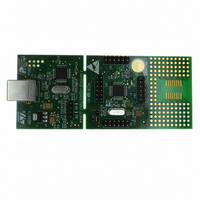
... Introduction The STM8S-DISCOVERY is a quick start evaluation board which helps you to discover the STM8 features, and to develop and share your own application based on an STM8S105 and includes an embedded debugger, ST-LINK, and a touch sensing button. Numerous applications are available from the STM8S-Discovery web page. ...
Page 2
... Contents Contents 1 Quick start . . . . . . . . . . . . . . . . . . . . . . . . . . . . . . . . . . . . . . . . . . . . . . . . . 3 2 Hardware and layout . . . . . . . . . . . . . . . . . . . . . . . . . . . . . . . . . . . . . . . . . 4 2.1 STM8S105C6T6 microcontroller . . . . . . . . . . . . . . . . . . . . . . . . . . . . . . . . 6 2.2 ST-LINK . . . . . . . . . . . . . . . . . . . . . . . . . . . . . . . . . . . . . . . . . . . . . . . . . . . 8 2.2.1 2.2.2 2.3 Power supply and power selection . . . . . . . . . . . . . . . . . . . . . . . . . . . . . . . 9 2.4 Single touch sensing . . . . . . . . . . . . . . . . . . . . . . . . . . . . . . . . . . . . . . . . 10 3 Daughterboard connection . . . . . . . . . . . . . . . . . . . . . . . . . . . . . . . . . . 11 4 Electrical schematics . . . . . . . . . . . . . . . . . . . . . . . . . . . . . . . . . . . . . . . 13 5 Revision history . . . . . . . . . . . . . . . . . . . . . . . . . . . . . . . . . . . . . . . . . . . 16 2/17 Using the ST-LINK . . . . . . . . . . . . . . . . . . . . . . . . . . . . . . . . . . . . . . . . . . 8 Using the ST-LINK on other STM8S applications . . . . . . . . . . . . . . . . . . 8 ...
Page 3
... UM0817 1 Quick start It is very simple to get started using the STM8S-DISCOVERY, just follow these four steps: 1. Connect the STM8S-DISCOVERY with a USB cable. 2. Press the TS1 button, and observe LED LD1 blinking. 3. Press the TS1 button to change blinking speed. 4. Visit www.st.com/stm8s-discovery and follow the tutorial, then discover other applications ...
Page 4
... Figure 2 illustrates the connections between the STM8S105C6T6 and its peripherals (ST- LINK, touch-sensing button, LED and connectors). Figure 3 helps you to locate these features on the STM8S-DISCOVERY board, as well as the potential point of separation (for more details refer to on other STM8S Figure 2. Hardware block diagram 4/17 applications) ...
Page 5
... Top layout USB connector ST-LINK JTAG USB data transfer LED ST-LINK core SWIM connector LED (LD1) Power supply jumper External Osc. (16 MHz) STM8S105C6T6 Touch sensing button (TS1) Wrapping area SO16 footprint Doc ID 16361 Rev 2 Hardware and layout Possible separation point 5/17 ...
Page 6
... UART with clock output for synchronous operation, Smartcard, IrDA, LIN – SPI interface Mbit/s – I2C interface up to 400 Kbit/s – Analog-to-digital converter 10-bit, ±1 LSB ADC with multiplexed channels 6/17 The STM8S105C6T6 8-bit microcontroller offers: 32 Kbytes of Flash program memory 1 Kbyte true data EEPROM 2 Kbytes RAM Doc ID 16361 Rev 2 UM0817 ...
Page 7
... UM0817 Figure 5. STM8S105 block diagram For more information see the STM8S105xx datasheet (Doc ID 14771) on the ST website. Doc ID 16361 Rev 2 Hardware and layout 7/17 ...
Page 8
... Hardware and layout 2.2 ST-LINK The ST-LINK provides a USB interface for programming and debugging using a single wire interface module (SWIM). The ST-LINK module of the STM8S-DISCOVERY also supplies 5 V and 3 the STM8S105C6T6 module. 2.2.1 Using the ST-LINK Figure 6. Typical configuration Note: The driver for ST-LINK is installed automatically when the USB is connected. ...
Page 9
... Power selection By removing this module you will lose power supply on the STM8S105C6T6 evaluation board. In consequence, you will not be able to program and use the STM8S105C6T6 board without a SWIM cable and an external power supply. To reconnect your STM8S105C6T6 use connector CNn see Section 3: Daughterboard connection ...
Page 10
... Hardware and layout 2.4 Single touch sensing A touch sensing button TS1 is available on the STM8S-DISCOVERY (see Figure 10. Touch sensing schematic To disable the touch sensing interface and to use PC1, PC2 and PC3 as standard I/O, you need to unsolder the 2-1 connection and solder 2-3 connection on SB4 and SB3, you also need to unsolder the R2 resistor ...
Page 11
... UM0817 3 Daughterboard connection Four 12-pin male headers CN1, CN2, CN3 and CN4 are connected to the STM8S105C6T6 microcontroller. See the following tables for pin assignments. Table 1. CN1 pinout Pin number Pin number (Cn1) (chip Table 2. CN2 pinout Pin number Pin number (Cn2) ...
Page 12
Daughterboard connection Table 3. CN3 pinout Pin number Pin number (Cn3) (chip Table 4. CN4 pinout Pin number Pin number (Cn4) (chip ...
Page 13
... Electrical schematics Figure 11. STM8S-DISCOVERY U_ST_LINK ST_LINK.SCHDOC RESET# ST_LINK_SWIM U_MCU MCU.SchDoc SB1 RESET# SB2 ST_LINK_SWIM STMicroelectronics Title: Number: STM8S-Discovery MB867 Rev: A.1(PCB.SCH) Date: 5/6/2009 Sheet ...
Page 14
... Figure 12. STM8S-DISCOVERY MCU 1 ST_LINK_SWIM VDD R7 10K[N/A] RESET# C1 10nF X1 16MHz NRST 1 NRST PA1 2 OSCIN/PA1 C3 PA2 3 OSCOUT/PA2 20pF 4 Vssio_1 5 Vss VCAP 6 VCAP C4 7 Vdd Vddio_1 PA3 9 C5 PA3 20pF PA4 10 PA4 PA5 11 PA5 680nF PA6 12 PA6 VDD L1 VDDA VDD BEAD C6 C7 1uF 100nF ...
Page 15
... Figure 13. STM8S-DISCOVERY ST-LINK (SWIM only) 1 +3V3 C15 C16 X2 20pF 1 2 20pF +3V3 8MHz 1 VBAT 2 PC13 3 PC14 SWIM_PULLUP_CTL 4 PC15 OSC_IN 5 OSC_IN OSC_OUT 6 OSC_OUT R16 STM_RST 7 +3V3 /RST 8 100K VSSA C11 9 +3V3 VDDA 100nF AIN_1 10 PA0 M25_CS 11 PA1 U2_TX 12 U2_TX CN5 8 7 STM_JRST ...
Page 16
Revision history 5 Revision history Table 5. Document revision history Date 05-Oct-2009 12-Feb-2010 16/17 Revision 1 Initial release. Section 2.4: RC acquisition principle 2 Doc ID 16361 Rev 2 UM0817 Changes modified. ...
Page 17
... UM0817 Information in this document is provided solely in connection with ST products. STMicroelectronics NV and its subsidiaries (“ST”) reserve the right to make changes, corrections, modifications or improvements, to this document, and the products and services described herein at any time, without notice. All ST products are sold pursuant to ST’s terms and conditions of sale. ...