C8051F120DK Silicon Laboratories Inc, C8051F120DK Datasheet - Page 180
C8051F120DK
Manufacturer Part Number
C8051F120DK
Description
DEVKIT-F120/21/22/23/24/25/26/27
Manufacturer
Silicon Laboratories Inc
Type
MCUr
Datasheet
1.C8051F120DK.pdf
(350 pages)
Specifications of C8051F120DK
Contents
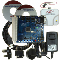
Evaluation Board, Power Supply, USB Cables, Adapter and Documentation
Processor To Be Evaluated
C8051F12x and C8051F13x
Interface Type
USB
Silicon Manufacturer
Silicon Labs
Core Architecture
8051
Silicon Core Number
C8051F120
Silicon Family Name
C8051F12x
Lead Free Status / RoHS Status
Contains lead / RoHS non-compliant
For Use With/related Products
C8051F120, 121, 122, 123, 124, 125, 126, 127
Lead Free Status / Rohs Status
Lead free / RoHS Compliant
Other names
336-1224
Available stocks
Company
Part Number
Manufacturer
Quantity
Price
Company:

Part Number:
C8051F120DK
Manufacturer:
SiliconL
Quantity:
4


C8051F120/1/2/3/4/5/6/7
C8051F130/1/2/3
reset is generated. The WDT can be enabled and disabled as needed in software, or can be permanently
enabled if desired. Watchdog features are controlled via the Watchdog Timer Control Register (WDTCN)
shown in SFR Definition 13.1.
13.7.1. Enable/Reset WDT
The watchdog timer is both enabled and reset by writing 0xA5 to the WDTCN register. The user's applica-
tion software should include periodic writes of 0xA5 to WDTCN as needed to prevent a watchdog timer
overflow. The WDT is enabled and reset as a result of any system reset.
13.7.2. Disable WDT
Writing 0xDE followed by 0xAD to the WDTCN register disables the WDT. The following code segment
illustrates disabling the WDT:
The writes of 0xDE and 0xAD must occur within 4 clock cycles of each other, or the disable operation is
ignored. This means that the prefetch engine should be enabled and interrupts should be disabled during
this procedure to avoid any delay between the two writes.
13.7.3. Disable WDT Lockout
Writing 0xFF to WDTCN locks out the disable feature. Once locked out, the disable operation is ignored
until the next system reset. Writing 0xFF does not enable or reset the watchdog timer. Applications always
intending to use the watchdog should write 0xFF to WDTCN in the initialization code.
13.7.4. Setting WDT Interval
WDTCN.[2:0] control the watchdog timeout interval. The interval is given by the following equation:
For a 3 MHz system clock, this provides an interval range of 0.021 ms to 349.5 ms. WDTCN.7 must be
logic 0 when setting this interval. Reading WDTCN returns the programmed interval. WDTCN.[2:0] reads
111b after a system reset.
180
4
3
CLR
MOV
MOV
SETB
+
WDTCN 2 0
EA
WDTCN,#0DEh
WDTCN,#0ADh
EA
–
T
sysclk
; disable all interrupts
; disable software watchdog timer
; re-enable interrupts
; where T
sysclk
is the system clock period.
Rev. 1.4
Related parts for C8051F120DK
Image
Part Number
Description
Manufacturer
Datasheet
Request
R

Part Number:
Description:
SMD/C°/SINGLE-ENDED OUTPUT SILICON OSCILLATOR
Manufacturer:
Silicon Laboratories Inc
Part Number:
Description:
Manufacturer:
Silicon Laboratories Inc
Datasheet:
Part Number:
Description:
N/A N/A/SI4010 AES KEYFOB DEMO WITH LCD RX
Manufacturer:
Silicon Laboratories Inc
Datasheet:
Part Number:
Description:
N/A N/A/SI4010 SIMPLIFIED KEY FOB DEMO WITH LED RX
Manufacturer:
Silicon Laboratories Inc
Datasheet:
Part Number:
Description:
N/A/-40 TO 85 OC/EZLINK MODULE; F930/4432 HIGH BAND (REV E/B1)
Manufacturer:
Silicon Laboratories Inc
Part Number:
Description:
EZLink Module; F930/4432 Low Band (rev e/B1)
Manufacturer:
Silicon Laboratories Inc
Part Number:
Description:
I°/4460 10 DBM RADIO TEST CARD 434 MHZ
Manufacturer:
Silicon Laboratories Inc
Part Number:
Description:
I°/4461 14 DBM RADIO TEST CARD 868 MHZ
Manufacturer:
Silicon Laboratories Inc
Part Number:
Description:
I°/4463 20 DBM RFSWITCH RADIO TEST CARD 460 MHZ
Manufacturer:
Silicon Laboratories Inc
Part Number:
Description:
I°/4463 20 DBM RADIO TEST CARD 868 MHZ
Manufacturer:
Silicon Laboratories Inc
Part Number:
Description:
I°/4463 27 DBM RADIO TEST CARD 868 MHZ
Manufacturer:
Silicon Laboratories Inc
Part Number:
Description:
I°/4463 SKYWORKS 30 DBM RADIO TEST CARD 915 MHZ
Manufacturer:
Silicon Laboratories Inc
Part Number:
Description:
N/A N/A/-40 TO 85 OC/4463 RFMD 30 DBM RADIO TEST CARD 915 MHZ
Manufacturer:
Silicon Laboratories Inc
Part Number:
Description:
I°/4463 20 DBM RADIO TEST CARD 169 MHZ
Manufacturer:
Silicon Laboratories Inc