C8051F120DK Silicon Laboratories Inc, C8051F120DK Datasheet - Page 28
C8051F120DK
Manufacturer Part Number
C8051F120DK
Description
DEVKIT-F120/21/22/23/24/25/26/27
Manufacturer
Silicon Laboratories Inc
Type
MCUr
Datasheet
1.C8051F120DK.pdf
(350 pages)
Specifications of C8051F120DK
Contents
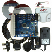
Evaluation Board, Power Supply, USB Cables, Adapter and Documentation
Processor To Be Evaluated
C8051F12x and C8051F13x
Interface Type
USB
Silicon Manufacturer
Silicon Labs
Core Architecture
8051
Silicon Core Number
C8051F120
Silicon Family Name
C8051F12x
Lead Free Status / RoHS Status
Contains lead / RoHS non-compliant
For Use With/related Products
C8051F120, 121, 122, 123, 124, 125, 126, 127
Lead Free Status / Rohs Status
Lead free / RoHS Compliant
Other names
336-1224
Available stocks
Company
Part Number
Manufacturer
Quantity
Price
Company:

Part Number:
C8051F120DK
Manufacturer:
SiliconL
Quantity:
4


C8051F120/1/2/3/4/5/6/7
C8051F130/1/2/3
1.1.3. Additional Features
Several key enhancements are implemented in the CIP-51 core and peripherals to improve overall perfor-
mance and ease of use in end applications.
The extended interrupt handler provides 20 interrupt sources into the CIP-51 (as opposed to 7 for the stan-
dard 8051), allowing the numerous analog and digital peripherals to interrupt the controller. An interrupt
driven system requires less intervention by the MCU, giving it more effective throughput. The extra inter-
rupt sources are very useful when building multi-tasking, real-time systems.
There are up to seven reset sources for the MCU: an on-board V
clock detector, a voltage level detection from Comparator0, a forced software reset, the CNVSTR0 input
pin, and the RST pin. The RST pin is bi-directional, accommodating an external reset, or allowing the inter-
nally generated POR to be output on the RST pin. Each reset source except for the V
Input pin may be disabled by the user in software; the V
pin. The Watchdog Timer may be permanently enabled in software after a power-on reset during MCU ini-
tialization.
The MCU has an internal, stand alone clock generator which is used by default as the system clock after
any reset. If desired, the clock source may be switched on the fly to the external oscillator, which can use a
crystal, ceramic resonator, capacitor, RC, or external clock source to generate the system clock. This can
be extremely useful in low power applications, allowing the MCU to run from a slow (power saving) exter-
nal crystal source, while periodically switching to the 24.5 MHz internal oscillator as needed. Additionally,
an on-chip PLL is provided to achieve higher system clock speeds for increased throughput.
28
(Port I/O)
XTAL1
XTAL2
CP0+
CP0-
Generator
Circuitry
Internal
Clock
OSC
Crossbar
PLL
Comparator0
CNVSTR
+
-
(CNVSTR
enable)
reset
Figure 1.7. On-Board Clock and Reset
enable)
(CP0
reset
Clock Select
System
Clock
Detector
Missing
Clock
(one-
shot)
Microcontroller
EN
Extended Interrupt
CIP-51
Core
Handler
V
Rev. 1.4
DD
EN
WDT
PRE
DD
Supply
Monitor
+
-
Software Reset
System Reset
monitor is enabled/disabled via the MONEN
DD
Timeout
Supply
Reset
monitor, a Watchdog Timer, a missing
(wired-OR)
Reset
Funnel
DD
monitor and Reset
RST
Related parts for C8051F120DK
Image
Part Number
Description
Manufacturer
Datasheet
Request
R

Part Number:
Description:
SMD/C°/SINGLE-ENDED OUTPUT SILICON OSCILLATOR
Manufacturer:
Silicon Laboratories Inc
Part Number:
Description:
Manufacturer:
Silicon Laboratories Inc
Datasheet:
Part Number:
Description:
N/A N/A/SI4010 AES KEYFOB DEMO WITH LCD RX
Manufacturer:
Silicon Laboratories Inc
Datasheet:
Part Number:
Description:
N/A N/A/SI4010 SIMPLIFIED KEY FOB DEMO WITH LED RX
Manufacturer:
Silicon Laboratories Inc
Datasheet:
Part Number:
Description:
N/A/-40 TO 85 OC/EZLINK MODULE; F930/4432 HIGH BAND (REV E/B1)
Manufacturer:
Silicon Laboratories Inc
Part Number:
Description:
EZLink Module; F930/4432 Low Band (rev e/B1)
Manufacturer:
Silicon Laboratories Inc
Part Number:
Description:
I°/4460 10 DBM RADIO TEST CARD 434 MHZ
Manufacturer:
Silicon Laboratories Inc
Part Number:
Description:
I°/4461 14 DBM RADIO TEST CARD 868 MHZ
Manufacturer:
Silicon Laboratories Inc
Part Number:
Description:
I°/4463 20 DBM RFSWITCH RADIO TEST CARD 460 MHZ
Manufacturer:
Silicon Laboratories Inc
Part Number:
Description:
I°/4463 20 DBM RADIO TEST CARD 868 MHZ
Manufacturer:
Silicon Laboratories Inc
Part Number:
Description:
I°/4463 27 DBM RADIO TEST CARD 868 MHZ
Manufacturer:
Silicon Laboratories Inc
Part Number:
Description:
I°/4463 SKYWORKS 30 DBM RADIO TEST CARD 915 MHZ
Manufacturer:
Silicon Laboratories Inc
Part Number:
Description:
N/A N/A/-40 TO 85 OC/4463 RFMD 30 DBM RADIO TEST CARD 915 MHZ
Manufacturer:
Silicon Laboratories Inc
Part Number:
Description:
I°/4463 20 DBM RADIO TEST CARD 169 MHZ
Manufacturer:
Silicon Laboratories Inc