DM240011 Microchip Technology, DM240011 Datasheet - Page 19
DM240011
Manufacturer Part Number
DM240011
Description
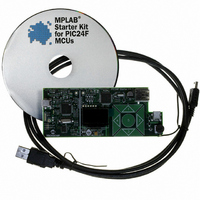
KIT STARTER MPLAB FOR PIC24F MCU
Manufacturer
Microchip Technology
Series
MPLAB®r
Type
MCUr
Datasheet
1.DM240011.pdf
(42 pages)
Specifications of DM240011
Contents
Board, Cable, CD
Processor To Be Evaluated
PIC24F
Data Bus Width
16 bit
Interface Type
USB
Silicon Manufacturer
Microchip
Core Architecture
PIC
Core Sub-architecture
PIC24
Silicon Core Number
PIC24F
Silicon Family Name
PIC24FJxxGBxxx
Kit Contents
Board Cables CD Docs
Lead Free Status / RoHS Status
Lead free / RoHS Compliant
For Use With/related Products
PIC24F
Lead Free Status / Rohs Status
Lead free / RoHS Compliant
Available stocks
Company
Part Number
Manufacturer
Quantity
Price
Company:

Part Number:
DM240011
Manufacturer:
Microchip Technology
Quantity:
135
Company:
Part Number:
DM240011
Manufacturer:
MICROCHIP
Quantity:
12 000


3.1
3.2
© 2008 Microchip Technology Inc.
OVERVIEW
STARTER KIT CONFIGURATIONS
Chapter 3. Configuring the Starter Kit Hardware
This chapter discusses how to configure the hardware of the MPLAB Starter Kit for
PIC24F for various USB prototypes. Topics covered include:
• Overview
• Starter Kit Configurations
In its default configuration, the application side of the starter kit functions as a USB
embedded host. Even though the board is drawing power from its connection to the
host PC as a bus-powered device, the demo application functions independently of the
host PC in communicating with USB peripheral devices.
However, the starter kit can also be used as a platform for developing USB device
(peripheral) applications. The mini-B receptacle (J4) on the application side provides
the interface for an external USB host.
When setting it up as a prototyping platform, the starter kit board can be configured as
either a USB embedded host or a USB device (peripheral). At the same time, the starter
kit can be configured to operate with or without the functionality of the
programmer/debugger. In terms of the MPLAB IDE environment, we can think of the
application as being in Debug or Release mode.
The hardware configurations described here cover the vast majority of cases that the
user is likely to see in developing USB applications. Other configurations and USB
applications may be possible.
3.2.1
This is the default configuration used when the starter kit is first connected to a host PC
(see Section 1.3 “Initial Board Setup”). It is also used when USB embedded host
applications are still being developed and debugged. In both instances, power to the
starter kit is provided through the USB cable.
3.2.2
In this configuration, application code for a USB device is still being developed and
debugged. This requires connections to both the programmer/debugger and
application sides of the board, using two A to mini-B USB cables (Figure 3-1):
1. Connected from the host PC to the programmer/debugger (J1).
2. Connected from the host PC to the application side (J5).
The programmer side cable provides the interface to MPLAB IDE, while the application
side cable provides the interface between the device and host applications. Both
cables provide power to the board.
Embedded Host, Debug Mode
Device, Debug Mode
MPLAB STARTER KIT FOR PIC24F
USER’S GUIDE
DS51725A-page 15
Related parts for DM240011
Image
Part Number
Description
Manufacturer
Datasheet
Request
R

Part Number:
Description:
Manufacturer:
Microchip Technology Inc.
Datasheet:
Part Number:
Description:
Manufacturer:
Microchip Technology Inc.
Datasheet:
Part Number:
Description:
Manufacturer:
Microchip Technology Inc.
Datasheet:
Part Number:
Description:
Manufacturer:
Microchip Technology Inc.
Datasheet:
Part Number:
Description:
Manufacturer:
Microchip Technology Inc.
Datasheet:
Part Number:
Description:
Manufacturer:
Microchip Technology Inc.
Datasheet:
Part Number:
Description:
Manufacturer:
Microchip Technology Inc.
Datasheet:
Part Number:
Description:
Manufacturer:
Microchip Technology Inc.
Datasheet: