EDB9315A-Z Cirrus Logic Inc, EDB9315A-Z Datasheet
EDB9315A-Z
Specifications of EDB9315A-Z
EDB9315A


Related parts for EDB9315A-Z


EDB9315A-Z Summary of contents
Page 1
... EDB9315A Engineering Development Board Technical Reference Manual http://www.cirrus.com Enhanced Universal Platform © Copyright 2006 Cirrus Logic, Inc. EP9315 System-on-Chip Processor DS638DB3 AUG ’06 ...
Page 2
... EDB9315A Technical Reference Manual CORPORATE HEADQUARTERS Cirrus Logic, Inc. 2901 Via Fortuna Austin, Texas 78746 United States Phone: (512) 851-4000 Phone: (800) 888-5016 INTERNATIONAL OFFICES ASIA PACIFIC Cirrus Logic Intl. Ltd. 20F, Ocean Building 80 Shanghai Street Kowloon, Hong Kong China Phone: (852) 2376-0801 ...
Page 3
... CORPORATE HEADQUARTERS . . . . . . . . . . . . . . . . . . . . . . . . . . . . . . . . . . . . . . . . . . . . . . .2 INTERNATIONAL OFFICES . . . . . . . . . . . . . . . . . . . . . . . . . . . . . . . . . . . . . . . . . . . . . . . . . . .2 ASIA PACIFIC . . . . . . . . . . . . . . . . . . . . . . . . . . . . . . . . . . . . . . . . . . . . . . . . . . . . . . . . . . . . . . . . . . . . . . . . 2 JAPAN . . . . . . . . . . . . . . . . . . . . . . . . . . . . . . . . . . . . . . . . . . . . . . . . . . . . . . . . . . . . . . . . . . . . . . . . . . . . . . 2 EUROPE . . . . . . . . . . . . . . . . . . . . . . . . . . . . . . . . . . . . . . . . . . . . . . . . . . . . . . . . . . . . . . . . . . . . . . . . . . . . 2 1. EDB9315A Kit Contents . . . . . . . . . . . . . . . . . . . . . . . . . . . . . . . . . . . . . . . . . . . . . . . . . . . . . . 5 2. Introducing the EDB9315A Engineering Development Board . . . . . . . . . . . . . . . . . . . . . . . 6 2.1 Identifying What's on the Board . . . . . . . . . . . . . . . . . . . . . . . . . . . . . . . . . . . . . . . . . . . . . . . . . . . . . . . 6 3. Getting Started . . . . . . . . . . . . . . . . . . . . . . . . . . . . . . . . . . . . . . . . . . . . . . . . . . . . . . . . . . . . . 8 3.1 Before you Begin... . . . . . . . . . . . . . . . . . . . . . . . . . . . . . . . . . . . . . . . . . . . . . . . . . . . . . . . . . . . . . . . . . 8 3.2 Attaching Cables . . . . . . . . . . . . . . . . . . . . . . . . . . . . . . . . . . . . . . . . . . . . . . . . . . . . . . . . . . . . . . . . . . . 8 3.3 Before Applying Power... . . . . . . . . . . . . . . . . . . . . . . . . . . . . . . . . . . . . . . . . . . . . . . . . . . . . . . . . . . . . . 8 4. EDB9315A Circuit Description . . . . . . . . . . . . . . . . . . . . . . . . . . . . . . . . . . . . . . . . . . . . . . . . 10 4 ...
Page 4
... EDB9315A Technical Reference Manual Figure 1. EDB9315A Board.......................................................................................................................5 Figure 2. EDB9315A Top View .................................................................................................................7 Figure 3. Block Diagram..........................................................................................................................10 Figure 4. Schematic Page 1 - Block Diagram .........................................................................................19 Figure 5. Schematic Page 2 - Processor & Memory ...............................................................................20 Figure 6. Schematic Page 3 - Peripherals ..............................................................................................21 Figure 7. Schematic Page 4 - UARTs & USB .........................................................................................22 Figure 8. Schematic Page Power ................................................................................................23 Figure 9. Schematic Page 6 - SDRAM & Flash ......................................................................................24 Figure 10. Schematic Page 7 - JTAG & ...
Page 5
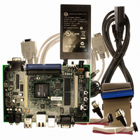
... EDB9315A Kit Contents Each EDB9315A kit comes with the following: • EDB9315A Development Board • Null Modem Serial Cable • Power Supply: +12V, 5A, 110V/220V with AC Power Cord • Quick Start Guide • Registration Card • (2) IDC10-to-DB9 Cables • IDE Ribbon Cable • ...
Page 6
... Expansion Connectors • LCD Interface with Touch Screen Support Note: The EDB9315A kit does not include a LCD screen. The LCD interface is pin-compatible with previous Cirrus Logic development boards. Not all features of the EP9315 are on the base board. Two high-density connectors have been provided to allow for daughter card expansion ...
Page 7
... Cirrus Logic download utility to put new code into Flash memory. DS638DB3 Figure 2. EDB9315A Top View N. USB Device Connector O. Ethernet Connector P. Dual, Stacked USB Host Connector Q. Audio Out Connector R. Audio In Connector S. Peripheral Bus Expansion Connector T. Touch Screen Connector U. JTAG Connector V. VGA Connector - DB15, female W ...
Page 8
... PCB for the pin 1 location. The pin 1 identifier is marked by either a number or a triangle. 3.3 Before Applying Power... In order to use the EDB9315A the user must first connect the peripherals to the EDB9315A as described in the following procedure. 1. Place the EDB9315A on a static free surface. ...
Page 9
... Qt/Opie desktop on the VGA monitor, depending which OS you have programmed into the board. The EDB9315A comes with WinCE 5.0 installed. NOTE: The WinCE 5.0 binary is not provided on the support web site. If you erase the image on the board, you will have to download the BSP provided by Cirrus Logic and compile it using Platform Builder ...
Page 10
... EDB9315A Technical Reference Manual 4. EDB9315A Circuit Description This chapter makes reference to the schematics in Appendix A and discusses the main circuit functionality of each schematic page. A detailed block diagram of the EDB9315A Engineering Development Board is shown below. Memory SDRAM Expansion 64 MByte 120 pin 32-bit POWER Vin = +12V Vout=1 ...
Page 11
... Two such cables are included with the kit. All UART signals are level shifted from TTL to RS-232. The CIR uses an enhanced GPIO (EGPIO) line to communicate to the EP9315 device. DS638DB3 for the latest board schematics. Look under the download link at the top of the © Copyright 2006 Cirrus Logic, Inc. EDB9315A Technical Reference Manual 11 ...
Page 12
... EDB9315A Technical Reference Manual Page 5 This is the power section for the EP9315 device. The ADC and PLL supplies are filtered. There is no reason to filter the 3.3 and the 1.8V power rails. Page 6 The SDRAM interface is comprised of two 16-bit SDRAM devices to form a 32-bit SDRAM bus. The SDRAM is connected to /SDCS0 and is located at physical memory address 0xC000_0000 ...
Page 13
... However if a CPLD or FPGA is attached there is no reason to buffer. Use proper engineering practices when using the high-speed memory bus with daughter cards. The Peripheral Expansion bus has the signals for features not implemented on the EDB9315A board and for commonly used signals. ...
Page 14
... Page 14 Power and reset circuits are shown on this page. Most of the changes made to this revision of the EDB9315A board were made in this section. The most important change made is that the board is now powered from a +12V power supply instead of the former +5V supply. The board has two connectors for input power. J10 is the standard power connector and is where the power supply provided in the kit attaches ...
Page 15
... Cirrus Logic provides complete source for its Linux 2.6 offering. The Cirrus Logic release images for the EDB9315A are also provided for those who do not want to build the toolchain and environment or want a quick way to load Linux onto the board. If, however, you wish to implement functionality other than that ...
Page 16
... EDB9315A Technical Reference Manual 6. Developer’s User Forum Many references have been made to the Cirrus Logic Developers User's Forum in this document. The Cirrus Logic Developers User's Forum is a company-sponsored site and moderated by Cirrus Logic employees. However not the technical help line for the Cirrus Logic ARM place where developers can share ideas and ask questions from others ...
Page 17
... AN273, “EP93xx Silicon Rev E Design Guidelines” • AN265, “EP93xx RTC Oscillator Circuit” • AN258, “EP93xx Power-up and Reset Lockup Workaround” Board Information The following information is located on the • EDB9315A Technical Reference Manual • Schematics • BOM • Artwork and PCB stackup Code Information The following information is located on the • ...
Page 18
... EDB9315A Technical Reference Manual Appendix A. Schematics The schematics for the EDB9315A Development Board are located on the Cirrus Logic Developer’s Forum website ( arm.cirrus.com (PDF) and PADS™ format. OrCAD™ versions of the schematics are not available The schematics are provided in Adobe’s portable document format © ...
Page 19
... DS638DB3 © Copyright 2006 Cirrus Logic, Inc. EDB9315A Technical Reference Manual 19 ...
Page 20
... EDB9315A Technical Reference Manual 20 © Copyright 2006 Cirrus Logic, Inc. DS638DB3 ...
Page 21
... DS638DB3 © Copyright 2006 Cirrus Logic, Inc. EDB9315A Technical Reference Manual 21 ...
Page 22
... EDB9315A Technical Reference Manual 22 © Copyright 2006 Cirrus Logic, Inc. DS638DB3 ...
Page 23
... DS638DB3 © Copyright 2006 Cirrus Logic, Inc. EDB9315A Technical Reference Manual 23 ...
Page 24
... EDB9315A Technical Reference Manual 24 © Copyright 2006 Cirrus Logic, Inc. DS638DB3 ...
Page 25
... DS638DB3 © Copyright 2006 Cirrus Logic, Inc. EDB9315A Technical Reference Manual 25 ...
Page 26
... EDB9315A Technical Reference Manual 26 © Copyright 2006 Cirrus Logic, Inc. DS638DB3 ...
Page 27
... DS638DB3 © Copyright 2006 Cirrus Logic, Inc. EDB9315A Technical Reference Manual 27 ...
Page 28
... EDB9315A Technical Reference Manual 28 © Copyright 2006 Cirrus Logic, Inc. DS638DB3 ...
Page 29
... DS638DB3 © Copyright 2006 Cirrus Logic, Inc. EDB9315A Technical Reference Manual 29 ...
Page 30
... EDB9315A Technical Reference Manual 30 © Copyright 2006 Cirrus Logic, Inc. DS638DB3 ...
Page 31
... DS638DB3 © Copyright 2006 Cirrus Logic, Inc. EDB9315A Technical Reference Manual 31 ...
Page 32
... EDB9315A Technical Reference Manual 32 © Copyright 2006 Cirrus Logic, Inc. DS638DB3 ...
Page 33
... E. PC Software • TFTP software F. Hardware • VGA monitor for the EDB9315A board Note: The instructions and screen shots in this Appendix make reference to the SolarWinds 6.0 TFTP server program. This program is not provided by Cirrus Logic. Other TFTP server programs may work equally well but will need to be verified by the developer. ...
Page 34
... EDB9315A Technical Reference Manual Downloading Files 1. Make a directory called "TFTPROOT" on C:\ 2. Use a computer that has an Internet connection and download the files specified in "D. Software" to the directory made in step 1. 3. Disconnect the Ethernet cable if using Wired Ethernet. Plug in the Ethernet cross-over cable into the computer's Ethernet port ...
Page 35
... Once the program is installed, run the TFTP Server program. 4. Configure the TFTP Root directory to point to C:\TFTPROOT. 5. Select the Security Tab and make sure the Client access is Transmit and Receive files. See the pictures below. DS638DB3 © Copyright 2006 Cirrus Logic, Inc. EDB9315A Technical Reference Manual 35 ...
Page 36
... Server is "listening" located in the lower right. Note: Note: You may get an IP address of 127.0.0.1 because the EDB9315A board does not have the boot loader code programmed yet. This is ok. Simply quit the TFTP server program. Instructions on when to start the program will be given during the board programming section ...
Page 37
... NO hardware control flow. It should look like the picture below when complete. Note you have to "Disconnect" in order to make configuration changes. Click "Call" once the configuration is complete. DS638DB3 © Copyright 2006 Cirrus Logic, Inc. EDB9315A Technical Reference Manual 37 ...
Page 38
... EDB9315A Technical Reference Manual Board Programming Setup 1. At this point, the RJ45 Ethernet port on the Windows PC is configured, HyperTerminal is running, the TFTP server is running, the Cirrus Logic software has been downloaded to the C:\TFTPROOT directory and the board is powered up. 2. Connect one end of the Null Modem cable to J2. ...
Page 39
... Erasing then Programming the Flash Memory download.exe Successfully Programming redboot.bin DS638DB3 download.exe Downloading the Code © Copyright 2006 Cirrus Logic, Inc. EDB9315A Technical Reference Manual 39 ...
Page 40
... EDB9315A Technical Reference Manual 3. Redboot.bin has been programmed into Flash memory HyperTerminal and re-establish serial communication to the board by pressing the Call button. 4. Press and release pushbutton S3, /POR. The board will reboot and eventually display information in the HyperTerminal window. Note: The initial error about configuration checksum error is expected for a brand new board or a board where the Flash device has been completely erased ...
Page 41
... Press and release pushbutton S3 "/POR" for the changes to take effect. You should see the following. Note: It will say "No image 'image_name' found". That is ok for now. We have not downloaded and programmed those images into Flash yet DS638DB3 © Copyright 2006 Cirrus Logic, Inc. EDB9315A Technical Reference Manual 41 ...
Page 42
... EDB9315A Technical Reference Manual 10. Execute the following command: load - 0xa00000 ramdisk.gz 11. You will see a spinning character in the bottom left hand side of the window. Wait until the RedBoot> prompt returns. 12. Next type: fis create -b 0xa00000 -l 0xa00000 ramdisk 13. This command will program the ramdisk.gz file into a Flash partition called ramdisk. Wait until the RedBoot> ...
Page 43
... Once the board has been programmed, reset the board and wait for it to boot up. You will see the following (or similar) screen on the display.. DS638DB3 © Copyright 2006 Cirrus Logic, Inc. EDB9315A Technical Reference Manual 43 ...
Page 44
... EDB9315A Technical Reference Manual Revision History Revision Date DB1 DEC 2005 First release. DB2 AUG 2006 Updated for Rev C PCB. Reference designator S2 changed to S1 (power switch). Rev C board is identified by the revision level printed next to the serial number on the backside of the PCB under the UART0 connector, J2. ...