C8051F005DK Silicon Laboratories Inc, C8051F005DK Datasheet - Page 117
C8051F005DK
Manufacturer Part Number
C8051F005DK
Description
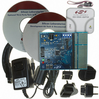
DEV KIT FOR F005/006/007
Manufacturer
Silicon Laboratories Inc
Type
MCUr
Datasheet
1.C8051F005-TB.pdf
(171 pages)
Specifications of C8051F005DK
Contents
Evaluation Board, Power Supply, USB Cables, Adapter and Documentation
Processor To Be Evaluated
C8051F01x
Interface Type
USB
Silicon Manufacturer
Silicon Labs
Core Architecture
8051
Silicon Core Number
C8051F005
Silicon Family Name
C8051F00x
Lead Free Status / RoHS Status
Contains lead / RoHS non-compliant
For Use With/related Products
Silicon Laboratories C8051 F005/006/007
Lead Free Status / Rohs Status
Lead free / RoHS Compliant
Other names
336-1188
Available stocks
Company
Part Number
Manufacturer
Quantity
Price
Company:

Part Number:
C8051F005DK
Manufacturer:
SiliconL
Quantity:
1


16.6.1. Control Register
The SMBus Control register SMB0CN is used to configure and control the SMBus interface. All of the bits in the
register can be read or written by software. Two of the control bits are also affected by the SMBus hardware. The
Serial Interrupt flag (SI, SMB0CN.3) is set to logic 1 by the hardware when a valid serial interrupt condition occurs.
It can only be cleared by software. The Stop flag (STO, SMB0CN.4) is cleared to logic 0 by hardware when a
STOP condition is present on the bus.
Setting the ENSMB flag to logic 1 enables the SMBus interface. Clearing the ENSMB flag to logic 0 disables the
SMBus interface and removes it from the bus. Momentarily clearing the ENSMB flag and then resetting it to logic
1 will reset a SMBus communication. However, ENSMB should not be used to temporarily remove a device from
the bus since the bus state information will be lost. Instead, the Assert Acknowledge (AA) flag should be used to
temporarily remove the device from the bus (see description of AA flag below).
Setting the Start flag (STA, SMB0CN.5) to logic 1 will put the SMBus in a master mode. If the bus is free, the
SMBus hardware will generate a START condition. If the bus is not free, the SMBus hardware waits for a STOP
condition to free the bus and then generates a START condition after a 5s delay per the SMB0CR value. (In
accordance with the SMBus protocol, the SMBus interface also considers the bus free if the bus is idle for 50s and
no STOP condition was recognized.) If STA is set to logic 1 while the SMBus is in master mode and one or more
bytes have been transferred, a repeated START condition will be generated. To ensure proper operation, the STO
flag should be explicitly cleared before setting STA to a logic 1.
When the Stop flag (STO, SMB0CN.4) is set to logic 1 while the SMBus interface is in master mode, the hardware
generates a STOP condition on the SMBus. In a slave mode, the STO flag may be used to recover from an error
condition. In this case, a STOP condition is not generated on the SMBus, but the SMBus hardware behaves as if a
STOP condition has been received and enters the “not addressed” slave receiver mode. The SMBus hardware
automatically clears the STO flag to logic 0 when a STOP condition is detected on the bus.
The Serial Interrupt flag (SI, SMB0CN.3) is set to logic 1 by hardware when the SMBus interface enters one of 27
possible states. If interrupts are enabled for the SMBus interface, an interrupt request is generated when the SI flag
is set. The SI flag must be cleared by software. While SI is set to logic 1, the clock-low period of the serial clock
will be stretched and the serial transfer is suspended.
The Assert Acknowledge flag (AA, SMB0CN.2) is used to set the level of the SDA line during the acknowledge
clock cycle on the SCL line. Setting the AA flag to logic 1 will cause an ACKNOWLEDGE (low level on SDA) to
be sent during the acknowledge cycle if the device has been addressed. Setting the AA flag to logic 0 will cause a
NOT ACKNOWLEDGE (high level on SDA) to be sent during acknowledge cycle. After the transmission of a
byte in slave mode, the slave can be temporarily removed from the bus by clearing the AA flag. The slave’s own
address and general call address will be ignored. To resume operation on the bus, the AA flag must be reset to logic
1 to allow the slave’s address to be recognized.
Setting the SMBus Free Timer Enable bit (FTE, SMB0CN.1) to logic 1 enables the SMBus Free Timeout feature. If
SCL and SDA remain high for the SMBus Free Timeout given in the SMBus Clock Rate Register (Figure 16.5), the
bus will be considered free and a Start will be generated if pending. The bus free period should be greater than
50s.
Setting the SMBus timeout enable bit (TOE, SMB0CN.0) to logic 1 enables Timer 3 to count up when the SCL line
is low and Timer 3 is enabled. If Timer 3 overflows, a Timer 3 interrupt will be generated, which will alert the CPU
that a SMBus SCL low timeout has occurred.
117
C8051F000/1/2/5/6/7
C8051F010/1/2/5/6/7
Rev. 1.7
Related parts for C8051F005DK
Image
Part Number
Description
Manufacturer
Datasheet
Request
R

Part Number:
Description:
SMD/C°/SINGLE-ENDED OUTPUT SILICON OSCILLATOR
Manufacturer:
Silicon Laboratories Inc
Part Number:
Description:
Manufacturer:
Silicon Laboratories Inc
Datasheet:
Part Number:
Description:
N/A N/A/SI4010 AES KEYFOB DEMO WITH LCD RX
Manufacturer:
Silicon Laboratories Inc
Datasheet:
Part Number:
Description:
N/A N/A/SI4010 SIMPLIFIED KEY FOB DEMO WITH LED RX
Manufacturer:
Silicon Laboratories Inc
Datasheet:
Part Number:
Description:
N/A/-40 TO 85 OC/EZLINK MODULE; F930/4432 HIGH BAND (REV E/B1)
Manufacturer:
Silicon Laboratories Inc
Part Number:
Description:
EZLink Module; F930/4432 Low Band (rev e/B1)
Manufacturer:
Silicon Laboratories Inc
Part Number:
Description:
I°/4460 10 DBM RADIO TEST CARD 434 MHZ
Manufacturer:
Silicon Laboratories Inc
Part Number:
Description:
I°/4461 14 DBM RADIO TEST CARD 868 MHZ
Manufacturer:
Silicon Laboratories Inc
Part Number:
Description:
I°/4463 20 DBM RFSWITCH RADIO TEST CARD 460 MHZ
Manufacturer:
Silicon Laboratories Inc
Part Number:
Description:
I°/4463 20 DBM RADIO TEST CARD 868 MHZ
Manufacturer:
Silicon Laboratories Inc
Part Number:
Description:
I°/4463 27 DBM RADIO TEST CARD 868 MHZ
Manufacturer:
Silicon Laboratories Inc
Part Number:
Description:
I°/4463 SKYWORKS 30 DBM RADIO TEST CARD 915 MHZ
Manufacturer:
Silicon Laboratories Inc
Part Number:
Description:
N/A N/A/-40 TO 85 OC/4463 RFMD 30 DBM RADIO TEST CARD 915 MHZ
Manufacturer:
Silicon Laboratories Inc
Part Number:
Description:
I°/4463 20 DBM RADIO TEST CARD 169 MHZ
Manufacturer:
Silicon Laboratories Inc