C8051F005DK Silicon Laboratories Inc, C8051F005DK Datasheet - Page 16
C8051F005DK
Manufacturer Part Number
C8051F005DK
Description
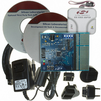
DEV KIT FOR F005/006/007
Manufacturer
Silicon Laboratories Inc
Type
MCUr
Datasheet
1.C8051F005-TB.pdf
(171 pages)
Specifications of C8051F005DK
Contents
Evaluation Board, Power Supply, USB Cables, Adapter and Documentation
Processor To Be Evaluated
C8051F01x
Interface Type
USB
Silicon Manufacturer
Silicon Labs
Core Architecture
8051
Silicon Core Number
C8051F005
Silicon Family Name
C8051F00x
Lead Free Status / RoHS Status
Contains lead / RoHS non-compliant
For Use With/related Products
Silicon Laboratories C8051 F005/006/007
Lead Free Status / Rohs Status
Lead free / RoHS Compliant
Other names
336-1188
Available stocks
Company
Part Number
Manufacturer
Quantity
Price
Company:

Part Number:
C8051F005DK
Manufacturer:
SiliconL
Quantity:
1


1.4.
The standard 8051 Ports (0, 1, 2, and 3) are available on the MCUs. All four ports are pinned out on the
F000/05/10/15. Ports 0 and 1 are pinned out on the F001/06/11/16, and only Port 0 is pinned out on the
F002/07/12/17. The Ports not pinned out are still available for software use as general purpose registers. The Port
I/O behave like the standard 8051 with a few enhancements.
Each Port I/O pin can be configured as either a push-pull or open-drain output. Also, the “weak pull-ups” which are
normally fixed on an 8051 can be globally disabled, providing additional power saving capabilities for low power
applications.
Perhaps the most unique enhancement is the Digital Crossbar. This is essentially a large digital switching network
that allows mapping of internal digital system resources to Port I/O pins on P0, P1, and P2. (See Figure 1.8.)
Unlike microcontrollers with standard multiplexed digital I/O, all combinations of functions are supported.
The on-board counter/timers, serial buses, HW interrupts, ADC Start of Conversion input, comparator outputs, and
other digital signals in the controller can be configured to appear on the Port I/O pins specified in the Crossbar
Control registers. This allows the user to select the exact mix of general purpose Port I/O and digital resources
needed for his particular application.
Programmable Digital I/O and Crossbar
Highest
Priority
Lowest
Priority
Latches
Port
SYSCLK
CNVSTR
Comptr.
Outputs
SMBus
T0, T1,
UART
P0
P1
P2
P3
PCA
SPI
Figure 1.8. Digital Crossbar Diagram
T2
(P0.0-P0.7)
(P1.0-P1.7)
(P2.0-P2.7)
(P3.0-P3.7)
8
8
8
8
2
4
2
6
2
6
Rev. 1.7
XBR2 Registers
XBR0, XBR1,
Crossbar
Decoder
Priority
Digital
8
8
8
PRT0CF, PRT1CF,
PRT2CF Registers
PRT3CF
Register
Cells
Cells
Cells
Cells
P0
I/O
P1
I/O
P2
I/O
P3
I/O
C8051F000/1/2/5/6/7
C8051F010/1/2/5/6/7
External
Pins
P0.0
P0.7
P1.0
P1.7
P2.0
P2.7
P3.0
P3.7
Highest
Priority
Lowest
Priority
16
Related parts for C8051F005DK
Image
Part Number
Description
Manufacturer
Datasheet
Request
R

Part Number:
Description:
SMD/C°/SINGLE-ENDED OUTPUT SILICON OSCILLATOR
Manufacturer:
Silicon Laboratories Inc
Part Number:
Description:
Manufacturer:
Silicon Laboratories Inc
Datasheet:
Part Number:
Description:
N/A N/A/SI4010 AES KEYFOB DEMO WITH LCD RX
Manufacturer:
Silicon Laboratories Inc
Datasheet:
Part Number:
Description:
N/A N/A/SI4010 SIMPLIFIED KEY FOB DEMO WITH LED RX
Manufacturer:
Silicon Laboratories Inc
Datasheet:
Part Number:
Description:
N/A/-40 TO 85 OC/EZLINK MODULE; F930/4432 HIGH BAND (REV E/B1)
Manufacturer:
Silicon Laboratories Inc
Part Number:
Description:
EZLink Module; F930/4432 Low Band (rev e/B1)
Manufacturer:
Silicon Laboratories Inc
Part Number:
Description:
I°/4460 10 DBM RADIO TEST CARD 434 MHZ
Manufacturer:
Silicon Laboratories Inc
Part Number:
Description:
I°/4461 14 DBM RADIO TEST CARD 868 MHZ
Manufacturer:
Silicon Laboratories Inc
Part Number:
Description:
I°/4463 20 DBM RFSWITCH RADIO TEST CARD 460 MHZ
Manufacturer:
Silicon Laboratories Inc
Part Number:
Description:
I°/4463 20 DBM RADIO TEST CARD 868 MHZ
Manufacturer:
Silicon Laboratories Inc
Part Number:
Description:
I°/4463 27 DBM RADIO TEST CARD 868 MHZ
Manufacturer:
Silicon Laboratories Inc
Part Number:
Description:
I°/4463 SKYWORKS 30 DBM RADIO TEST CARD 915 MHZ
Manufacturer:
Silicon Laboratories Inc
Part Number:
Description:
N/A N/A/-40 TO 85 OC/4463 RFMD 30 DBM RADIO TEST CARD 915 MHZ
Manufacturer:
Silicon Laboratories Inc
Part Number:
Description:
I°/4463 20 DBM RADIO TEST CARD 169 MHZ
Manufacturer:
Silicon Laboratories Inc